368 7 ELECTRONIC CONTROL SYSTEMS DIAGNOSTICS
ECI Circuit Diagnostics
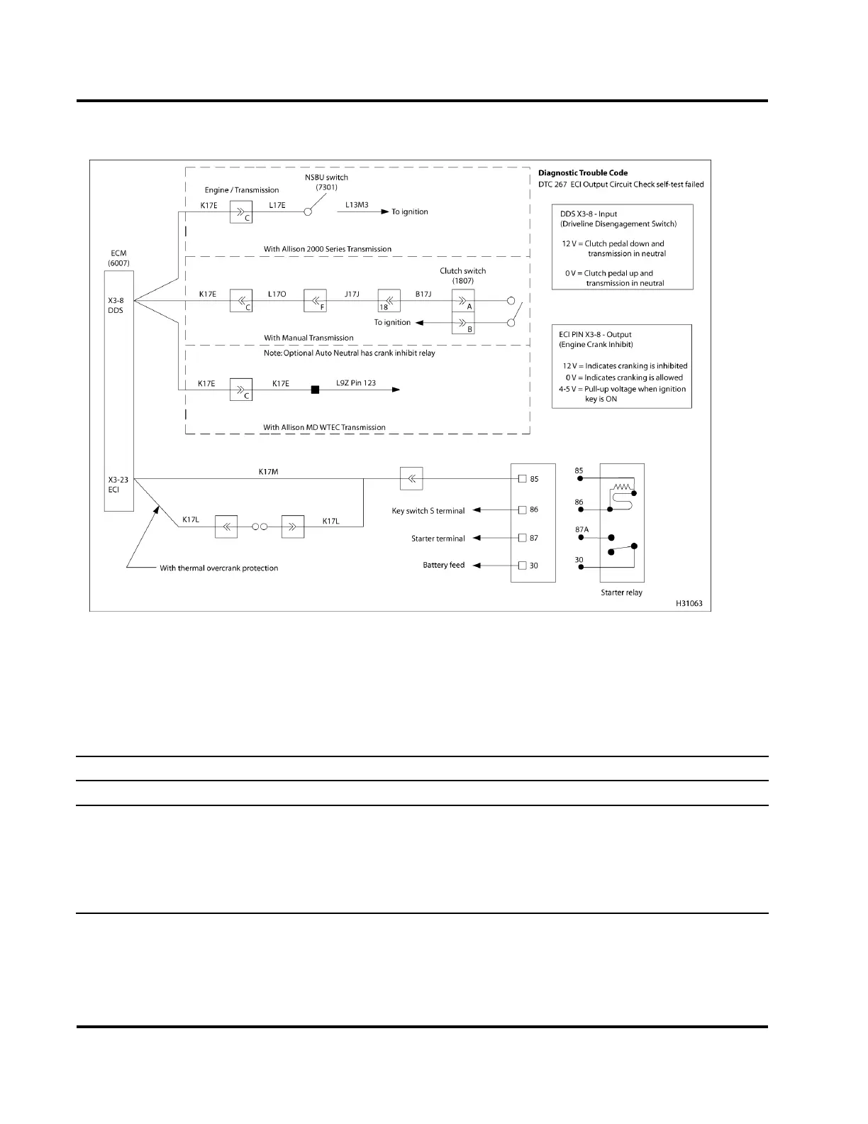
Figure 417 ECI circuit diagram
The ECI circuit requires the use of ve hicle circuit
diagrams. See truck Chassis E lectrical C ircuit
Diagram Manual for circuit numbers, connector and
fuse locations.
ECI Relay Voltage Checks (Turn the ignition switch to ON. Check with E CI relay removed.)
Test Point
Spec Comment
86 to gnd 12 V ±1.5 V
Check with relay disconnected and starter switch (key or button)
engaged. If no voltage present, troubleshoot ignition crank circuit.
30 to gnd 12 V ± 1.5 V
If no voltage is present, trouble sh oo t battery wiring.
85tognd 4Vto5V
ECMwillpullcircuitupto4Vto5VwithswitchONandgoto0Vwhen
the clutch is depressed or transmission is in neutral.
EGES-270-1
Read all safety instructions in the "Safety Information" section of this manual before doing any procedures.
Follow all warnings, cautions, and notes.
© August 2008 Navistar, Inc.
 Loading...


