1 ENGINE SYSTEMS 19
Air Management System
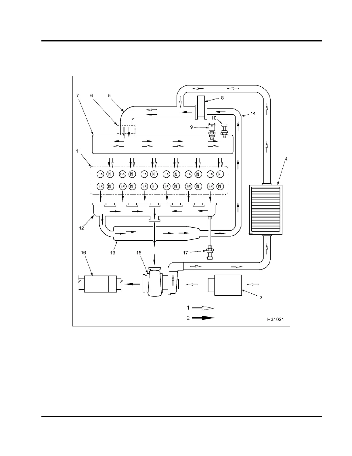
Air Management Components and Air Flow
Figure 10 Air Management System (AMS)
1. Intake air
2. Ex haust gas
3. Air filter assembly
4. Cha rge Air Cooler (CAC)
5. Inlet and EGR mixer duct
6. Inlet Air Heater (IAH) assembly
7. Intake manifold
8. EGR valve
9. Manifold Air Temperature (MAT)
sensor
10. Manifold Absolute Pressure
(MAP) sensor
11. Cylinder head
12. Exhaust manifold
13. EGR coo ler
14. Exhaust gas crossover
15. Variable Geometry Turbocharger
(VGT)
16. Muffler
17. Exhaust Back Pressure (EBP)
sensor
EGES-270-1
Read all safety instructions in the "Safety Information" section of this manual before doing any procedures.
Follow all warnings, cautions, and notes.
© August 2008 Navistar, Inc.
 Loading...


