7 ELECTRONIC CONTROL SYSTEMS DIAGNOSTICS 361
Tools
• EST with MasterDiagnostics® software
• EZ-Tech® interface cable
• Digital Multimeter (DMM)
• 3-Banana Plug Harness
• 500 Ohm Resistor Harness
• Breakout Box
• Breakout Harness
• Terminal Test Adapter Kit
EBP Operational Diagnostics
WARNING: To avoid serious personal injury,
possible death, or damage to the engine or vehicle
– comply with the following:
Be careful to avoid rotating parts (belts and fan)
and hot engine surfaces.
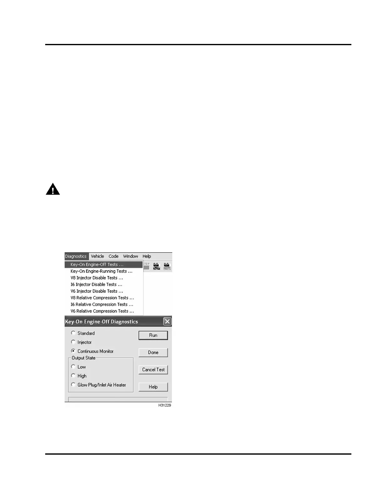
1. Using EST, open the D _ContinuousMonitor.ssn.
Figure 414 Continuous Monitor Test
2. To monitor signal voltage, run KOEO Continuous
Monitor Test. For help, see “Continuous Monitor
Test” in Section 3 (page 68).
3. Monitor EBP signal voltage. Verify an active DTC
for the EBP circuit.
4. Ifcodeisactive,dostep6and7tocheckcircuit
for the EBP sensor using the following table.
• Circuit Checks for EBP Sensor
5. If code is inactive, wiggle connectors and wires
at all suspected problem locations. If circuit
continuity is inte rrup ted, the EST will display
DTCs related to the condition.
6. Disconnect engine harness from pressure sensor.
NOTE: Inspect connectors for damaged pins,
corrosion, or loose pins. Repair if necessary.
7. Connect Pressure Sensor Breakout Harness to
engine harness only.
EGES-270-1
Read all safety instructions in the "Safety Information" section of this manual before doing any procedures.
Follow all warnings, cautions, and notes.
© August 2008 Navistar, Inc.
 Loading...


