272 6 PERFORMANCE DIAGNOSTICS
Monitoring BCP using VC Gasket Breakout
Harness
NOTE: Do this procedure, if an EST is not available.
This is an alternate method.
Tools
• VC Gasket Breakout Ha rness
•DMM
WARNING: To avoid serious personal injury,
possible death or damage to the engine or
vehicle, read all safety instructions in the “Safety
Information” section of this manual.
1. See “DT 466 Performance Specifications” –
Appendix A (page 595) ,“DT 570 and HT 570
Performance Specifications” – Appendix B (page
619) or Section 7 “Operational Voltages C hecks”
– for specifications and record on Diagnostic
Form.
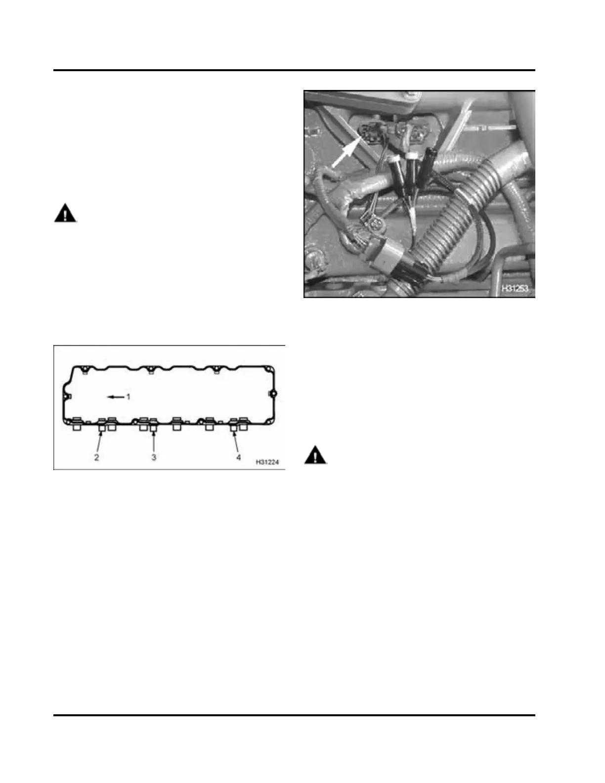
Figure 353 Valve cover gasket
1. Frontofengine
2. Pass-th rough connector for BCP sensor
3. Pass-through connector for brake shut-off valve
4. Pass-through connector for ICP sensor
2. Disconnect engine harness connector from the
pass-through connector for the BCP sensor and
complete steps 3 through 9.
Figure 354 VC Gasket Breakout Harness to
pass-through connector for BCP sensor
3. Connect VC Gasket Breakout Harness to the
pass-through connector for the BCP sensor and
engine harness.
4. Use DMM to me asure BCP.
• Connect POS to green (signal circuit) and
NEG to black (g ro und circuit).
WARNING: To avoid serious personal injury,
possible death or damage to the engine or vehicle
– comply with the following:
When routing DMM leads, do not crimp the leads,
run the leads too close to moving parts, or let
the leads touch hot engine surfaces. Secure the
DMM and leads in the cab so as not to obstruct
the operator.
5. Run DMM leads into cab.
6. Drive vehicle and make sure engine operating
temperature reaches 70 °C (158 °F).
7. Find a long, open stretch of road.
8. When driving conditions are safe, select a suitable
gear, press accelerator pedal fully to the floor, and
accelerate to rated speed at 100% load.
EGES-270-1
Read all safety instructions in the "Safety Information" section of this manual before doing any proced ures.
Follow all warnings, cautions, and notes.
©August 2008 Navistar, Inc.
 Loading...


