472 7 ELECTRONIC CONTROL SYSTEMS DIAGNOSTICS
ICP System (Inject ion Cont r ol Pressure)
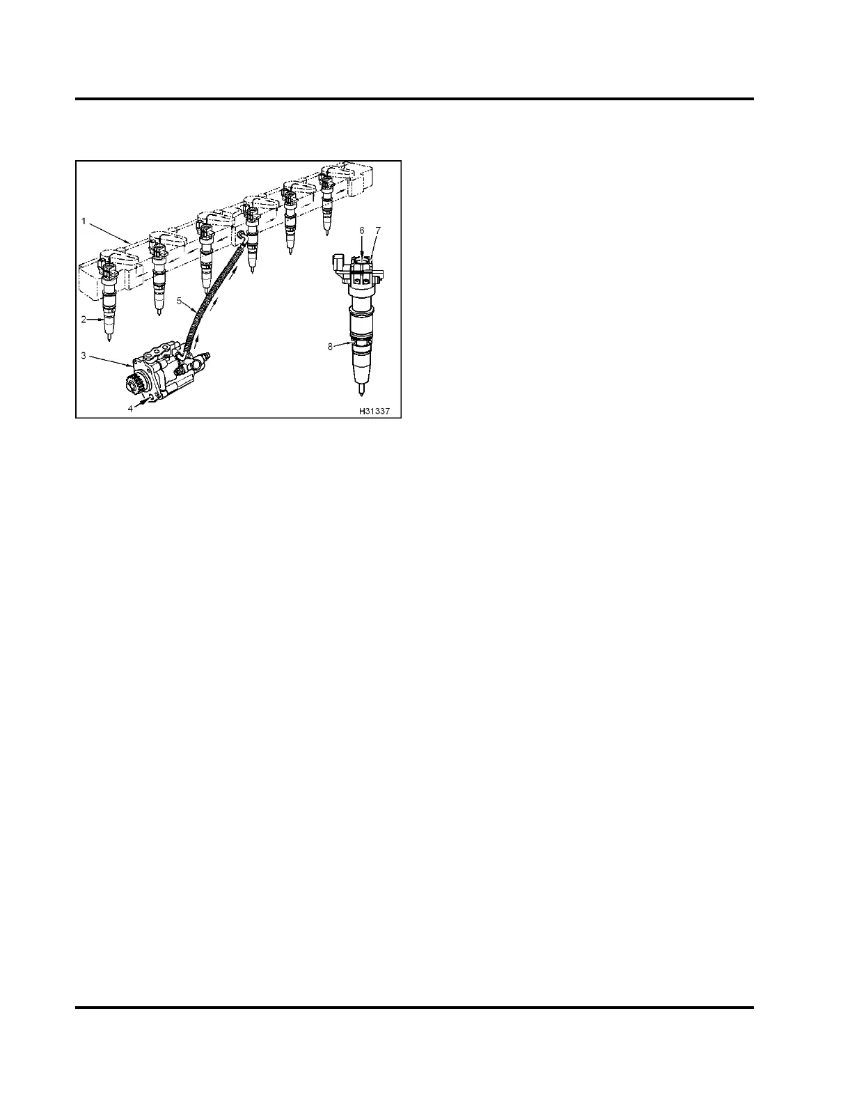
Figure 471 Function diagram for the ICP system
1. High-pressure oil manifold assembly
2. Fuel injector
3. High-pressure pump assembly
4. Oil inlet (lub e oil)
5. High-pressure oil hose
6. High -pressure oil inlet (inj ector)
7. Oil exhau st po rt (2)
8. Fuel inlet (4)
The ICP system additionally consists of th e following
subsystems and com ponents:
• Electronic Control Module (ECM)
• Injection Pressure Regulator (IPR)
• Injection Control Pressure (ICP) sensor
• Engine lubrication system
• Cylinder head passage
• High-pressure hydraulic pump
• High-pressure oil hose
• Associated wiring
• Diamond Logic® engine brake (optional)
Function
The function of the ICP s ystem is to develop,
maintain, and control the high-pressure injection
control pressure to provide the force to actuate the
injectors and provide fuel to the engine.
ICP System Operation
Fault Detection / Management
The Diagnostic Trouble Codes (DTCs) associated
with this system may indicate an electrical or
electronic control system failure, b ut will most
likely indicate a mechanical or hydraulic problem
with the ICP system.
The ECM continuously monitors the ICP in the
system to assure the control system is providing
the proper control pressure at all times. If the oil
pressure feedback provided by the ICP sensor does
not meet ECM desired values, the ECM will set a
DTC, illuminate the amber engine lamp and control
the operation of the ICP system by calculating the
correct oil pressure for all engine operating conditions
until the system is diagnosed and repaired.
The ECM monitors the injection control pressure
developed while the engine is cranking. When
pressure does not develop in an expected time frame,
the ECM will se t a DTC. The DT C will aid in identifying
and diagnosing the hard start and no start condition.
TheESTcanbeusedtocommandtheECMto
perform an engine running test on the ICP system.
TheECMcontrolstheIPRinaprogrammedsequence
and evaluates system performance. When the test
concludes, if a performance issue has been detected,
the ECM will set a DTC for that system condition.
When an ICP fault is detected, the ECM will default
to open loop of IPR control and the Electronic Service
Tool (EST) will display N/A on ICP data. ICP desired
will indicate default pressure.
ICP System Diagnostic Trouble Codes (DTCs)
DTCs are read using the EST or by counting the
flashes from the amber and red ENGINE lamp.
NOTE: Repair all injector, sensor, and actuator
DTCs before doing ICP diagnostic checks and
tests. Se e “Injectio n Control Pressure (ICP) System
Components and High-Pressure Oil Flow” – Section
1 (page 27) for additional information.
NOTE: Engine brake components need to be
considered during ICP diagnostics. See “Injection
Control Pressure (ICP) System Components and
High-Pressure Oil Flow” – Section 1 (page 27) for
additional information.
EGES-270-1
Read all safety instructions in the "Safety Information" section of this manual before doing any procedures.
Follow all warnings, cautions, and notes.
© August 2008 Navistar, Inc.
 Loading...


