312 7 ELECTRONIC CONTROL SYSTEMS DIAGNOSTICS
ATA Pin-Point Diagnostics
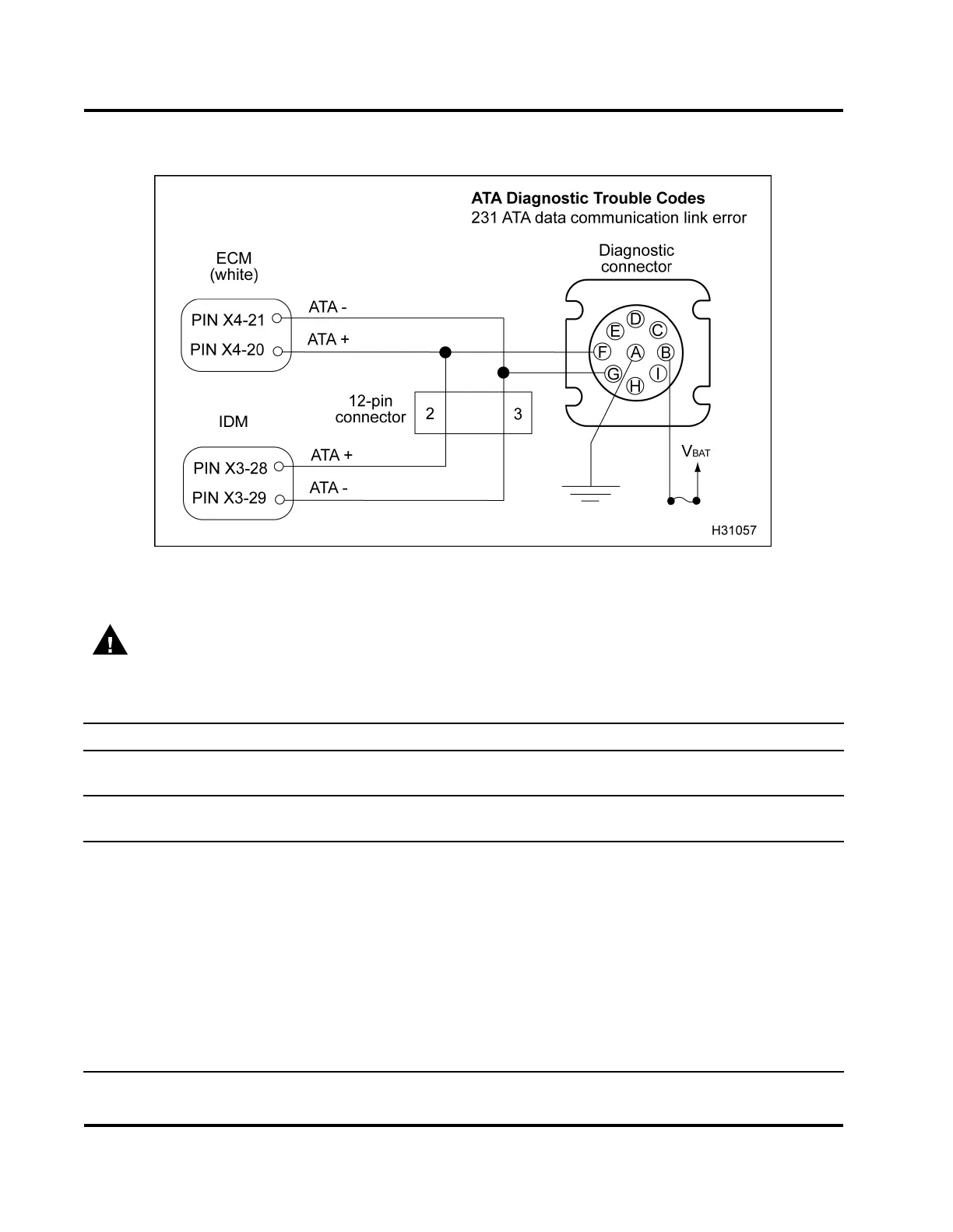
Figure 382 ATA circuit diagram
WARNING: To avoid serious personal injury, possible death, or damage to the engine or vehicle,
always disconnect main negative battery cable first. Always connect the main negative battery cable
last.
Diagnostic Connector Voltage Checks (Key-on engine-off.)
Test Point
Spec Signal Comment
BtoA B+ Voltage
Should be voltage at B at all times. If no voltage
is present, check ground and power circuits.
Diagnostic Connector to Chassis Ground (Turn the ignition switch to OFF and disconnect negative
battery cable.)
F to gnd
>1kΩ
ATA +
Gtognd >1kΩ
ATA –
If < 1 kΩ, check for short to ground through
harness or internal within the ECM and IDM.
Disconnect ECM and IDM and measure ground
again. If short is still present, disconnect other
devices connected to data communication
link and retes t. If short is still present, repair
harness.
Btognd
>1kΩ
Power
With fuse removed, if< 1 kΩ, check for short
to ground.
Atognd
<5Ω
gnd
If > 5 Ω, check for an open circuit. The EST
tool will not communicate.
EGES-270-1
Read all safety instructions in the "Safety Information" section of this manual before doing any procedures.
Follow all warnings, cautions, and notes.
© August 2008 Navistar, Inc.
 Loading...


