7 ELECTRONIC CONTROL SYSTEMS DIAGNOSTICS 413
EGR Actuator (Exhaust Gas Recirculation)
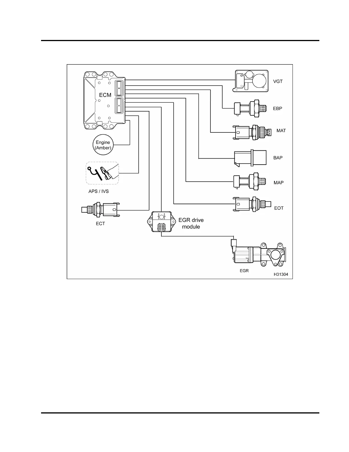
Figure 441 Function diagram for the EGR actuator
The function diagram for the EGR actuator includes
the follow i ng:
• Electronic Control Module (ECM)
• Variable Geometry Turbocharger (VGT) actuator
• Accelerator Position Sensor (APS)
• EGR actuator with position sensors
• EGR drive module
• Exhaust Back Pressure (EBP) sensor
• Manifold Absolute Temperature (MAT) sensor
• Barometric Absolute Pressure (BAP) sensor
• Engine Coolant Temperature (ECT) sensor
• Engine Oil Temperature (EOT) sensor
• Manifold Absolute Pressure (MAP) sensor
• ENGINE lamp (amber)
Function
The EGR actuator consists of three major
components, a valve, an actuator motor, and
Integrated Circuit (IC). The IC has three Hall effect
position sensors to monitor valve movement. The
EGR actuator is located at the front of the engine on
the mixer duct.
EGES-270-1
Read all safety instructions in the "Safety Information" section of this manual before doing any procedures.
Follow all warnings, cautions, and notes.
© August 2008 Navistar, Inc.
 Loading...


