7 ELECTRONIC CONTROL SYSTEMS DIAGNOSTICS 417
EGR Pin-Point Diagnostics
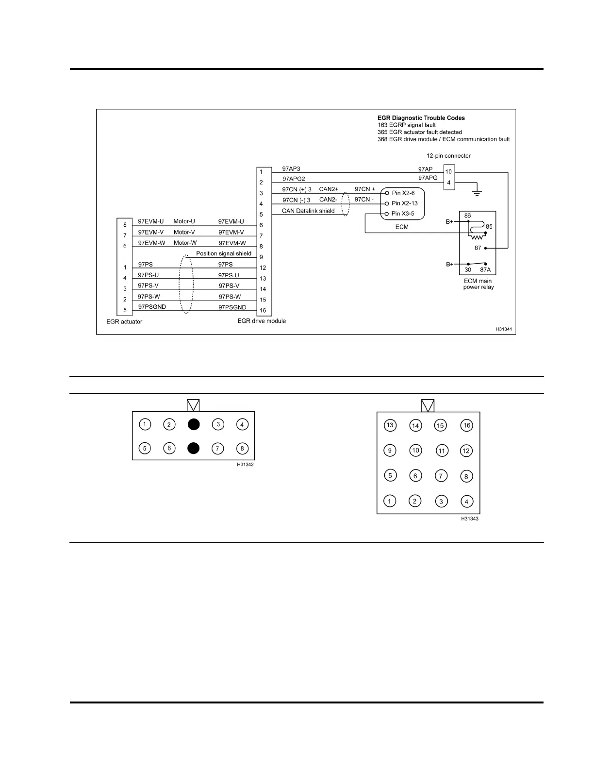
Figure 443 EGR circuit diagram
EGR Actuator Connector Pins EGR Drive Module Connector Pins
NOTE: Harness connectors shown with mating end
view.
Pin Pin Pin
1 Position sensor power 1 Power 9
Ground shield
2 Position sensor W 2
Ground
10 Not used
3 Position sensor V 3
CAN
high
11 Not used
4 Position sensor U 4
CAN
low
12 Position sensor power
5
Position sensor ground
5
CAN
shield
13 Position sensor U
6 Motor W 6 Motor
U
14 Position sensor V
EGES-270-1
Read all safety instructions in the "Safety Information" section of this manual before doing any procedures.
Follow all warnings, cautions, and notes.
© August 2008 Navistar, Inc.
 Loading...


