7 ELECTRONIC CONTROL SYSTEMS DIAGNOSTICS 539
V
REF
(Reference Voltage)
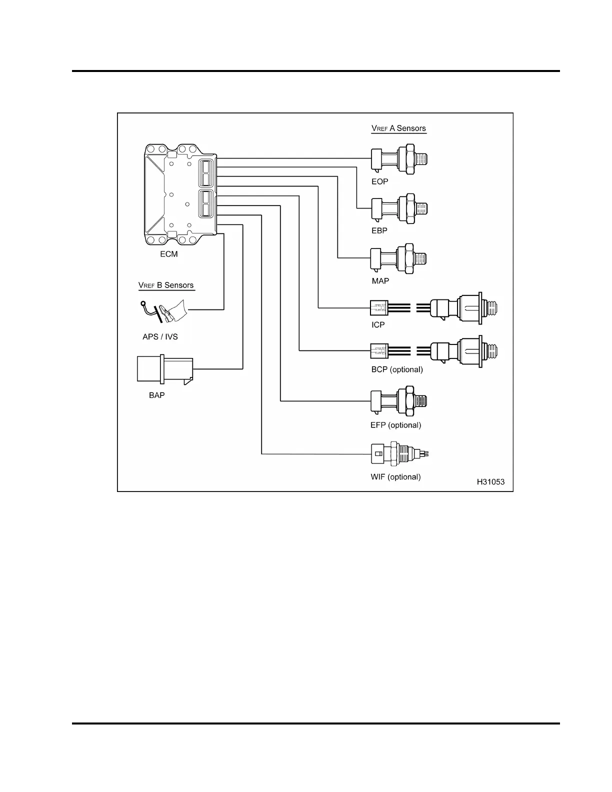
Figure 505 Function diagram for the V
REF
The function diagram for the V
REF
includes the
following:
• Engine Oil Pressure (EOP) sensor
• Exhaust Back Pressure (EBP) sensor
• Manifold Absolute P ressure (MAP) sensor
• Injection Control Pressure (ICP) sensor
• Brake Control Pressure (BCP) sensor (option a l)
• Engine Fuel Pressure (EFP) sensor (optional)
• Water in Fuel (WIF) sensor (optional)
• Accelerator Position Sensor (APS)
• Barometric Absolute Pressure (BAP) sensor
• Electronic Control Module (ECM)
Function
The ECM contains a regulated 5 V DC voltage
reference source to power engine and vehicle
sensors. The sensor signals are c ompared to th e
V
REF
to determine actual sensor output signal values.
These values are processed by the ECM for engine
operation.
EGES-270-1
Read all safety instructions in the "Safety Information" section of this manual before doing any procedures.
Follow all warnings, cautions, and notes.
© August 2008 Navistar, Inc.
 Loading...


