7 ELECTRONIC CONTROL SYSTEMS DIAGNOSTICS 403
Fan Air Solenoid Circuit Operation
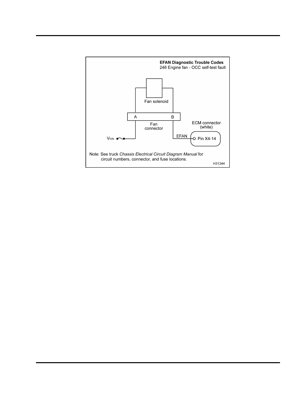
Figure 436 Fan air solenoid circuit diagram
The presence of air pres sure locks the fan clutch into
place an d allows fan activation and cooling.
When the fan needs to be activated, the ground is
removed from ECM Pin X4–14. The air fan solenoid
is deenergized and stops the flow of compressed air
tothefanclutch. Thefanclutchlocksthefanwhen
compressed a ir is not present.
When the fan needs to be deactivated, Pin X4–14
is grounded from the ECM. The air fan solenoid is
energized and allows compressed air to flow to the
fan clutch. The fan clutch unlocks the fan when
compressed air is present.
Fault Detection / Management
An open or short to ground in the EFAN can be
detected by the ECM during an on-demand engine
standard test. T he IAT and ECT are monitored
continuously. If a DTC is detected in the IAT or ECT,
the EFAN control is disabled and the engine fan is on
all the time.
NOTE: Before diagnosing, check that ECM is
programmed correctly. Verify vehicle / application
has an electronic fan.
EFAN Diagnostic Trouble Codes (DTCs)
DTCs are read using the EST or by counting the
flashes from the amber and red ENGINE lamp.
DTC 246
Engine Fan - OCC self-test fault
• DTC 246 is set by the ECM only during the KOEO
Standard Test. During this test the ECM performs
an output circuit test that momentarily enables the
EFAN solenoid and measures the voltage drop
across the relay
Tools
• EST with MasterDiagnostics® software
• EZ-Tech® interface cable
• Digital Multimeter (DMM)
EGES-270-1
Read all safety instructions in the "Safety Information" section of this manual before doing any procedures.
Follow all warnings, cautions, and notes.
© August 2008 Navistar, Inc.
 Loading...


