318 7 ELECTRONIC CONTROL SYSTEMS DIAGNOSTICS
BCP Sensor (Brake Control Pressure)
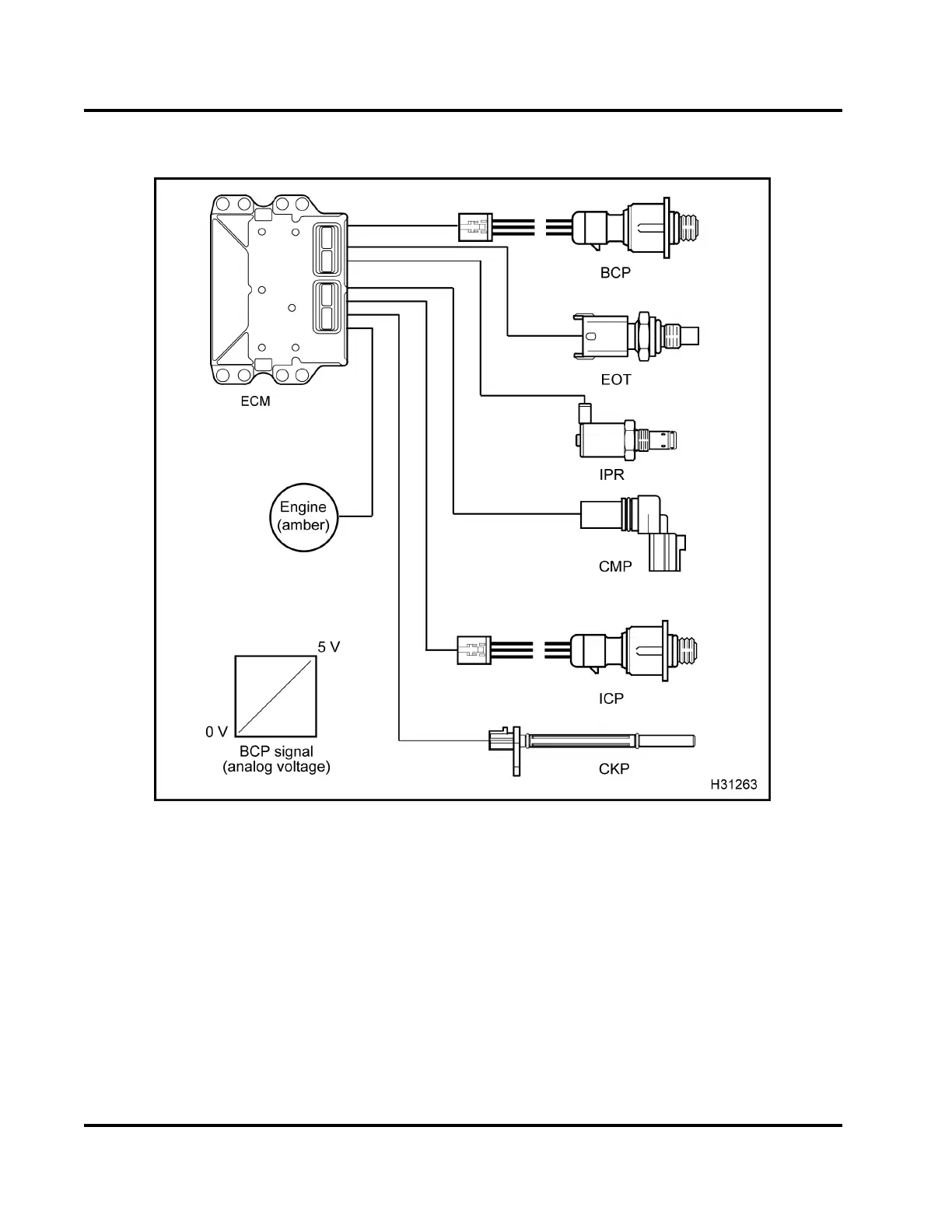
Figure 386 Functio
n diagram for the BCP sensor
Thefunctiondia
gram for the BCP sensor includes the
following:
• BCP sensor
• Injection Cont
rol Pressure (ICP) sensor
• Camshaft Positi
on (CMP) sensor
• Crankshaft Posi
tion (CKP) sensor
• Injection Press
ure Regulator (IPR)
•ElectronicCont
rol Module (ECM)
• Engine Oil Tempe
rature (EOT) s ensor
• ENGINE lamp (amb
er)
Function
The BCP sensor is
a Micro Strain Gauge (MSG )
sensor. The BCP
sensor is under the valve cover,
forward of the N
o. 2 fuel injector in the high-pressure
oil rail. Th e e
ngine harness connection on the valve
cover gasket
for the BCP sensor is left of the No. 2
injector con
nector. The ECM supplies a 5 V reference
signal whic
h the BCP sensor uses to produce a linear
analog vol
tage that indicates pressure.
EGES-270-1
Read all safety instructions in the "Safety Information" section of this manual before doing any procedures.
Follow all warnings, cautions, and notes.
© August 2008 Navistar, Inc.
 Loading...


