544 7 ELECTRONIC CONTROL SYSTEMS DIAGNOSTICS
VSS (Vehicle Speed Sensor)
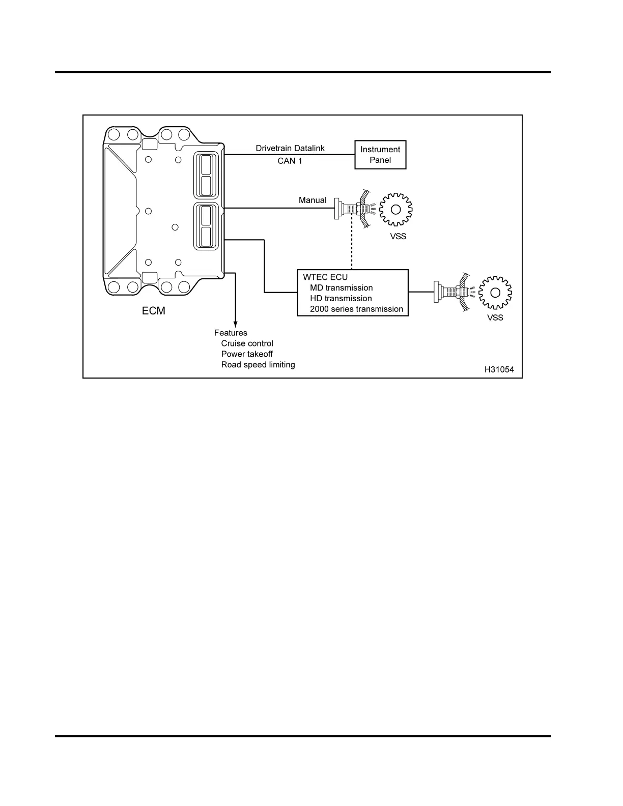
Figure 507 Function diagram fo
r the VSS
The function diagram for the
VSS includes the
following:
• VSS
• Electronic Control Modul
e(ECM)
• World Transmission Electr
onic Control (WTEC)
ECM
• Cruise Control
• Power Takeoff
• Road Speed Limit
Function
The VSS is on the left sid
e of the transmission. The
VSS reads the rotation
of a 16 toothed gear and
produces a sine wave signal.
The ECM processes
thesinewavesignaltocal
culate vehicle speed. The
Drivetrain Datalink (CA
N 1) tra nsmits the calcu lated
speed to the speedomete
r. The calculated speed
also assists in control
strategies that include Cruise
Control, Power Takeof
f, and Road Speed Limiting.
Allison WTEC MD, HD, an
d 2000 series transmissions
use an internal VSS t
hat sends a signal to the
transmission modul
e. The transmission module
processes the sign
al and sends a square wave signal
to the engine ECM.
EGES-270-1
Read all safety instructions in the "Safety Information" section of this manual before doing any procedures.
Follow all warnings, cautions, and notes.
© August 2008 Navistar, Inc.
 Loading...


