40 1 ENGINE SYSTEMS
Cooling System
Cooling System C omponents and Coolant Flow
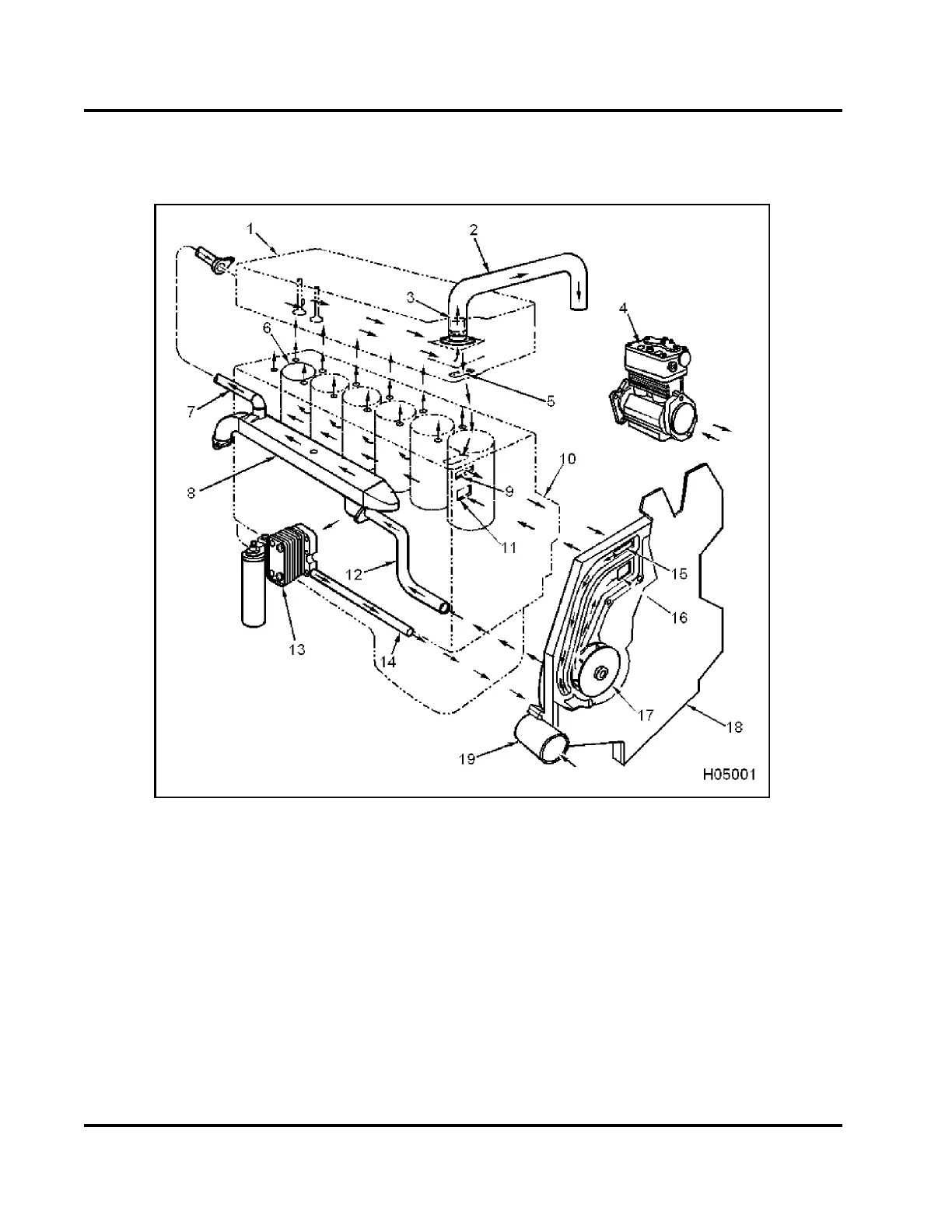
Figure 33 Engine cooling system
1. Cylinder head assembly
2. Water outlet t ube assembly
(thermostat outlet)
3. Thermostat assembly
4. Air compressor
5. Water return from cylinder head
to crankcase
6. Cylinder sleeve
7. EGR cooler return tube
assembly
8. EGR cooler asse mbl y
9. Water outlet from crankcase to
front cover
10. Crankcase
11. Water inlet to crankcase
12. EGR cooler supply tube
13. Oil mo dule assembly
14. Oil cooler tube
15. Water inlet to front cover and
water pump
16. Water supply from front cover t o
crankcase
17. Water pump impeller assembly
18. Front cover
19. Water inlet elbow
EGES-270-1
Read all safety instructions in the "Safety Information" section of this manual before doing any procedures.
Follow all warnings, cautions, and notes.
© August 2008 Navistar, Inc.
 Loading...


