400 7 ELECTRONIC CONTROL SYSTEMS DIAGNOSTICS
Fan Clutch Pin-Point Diagnostics
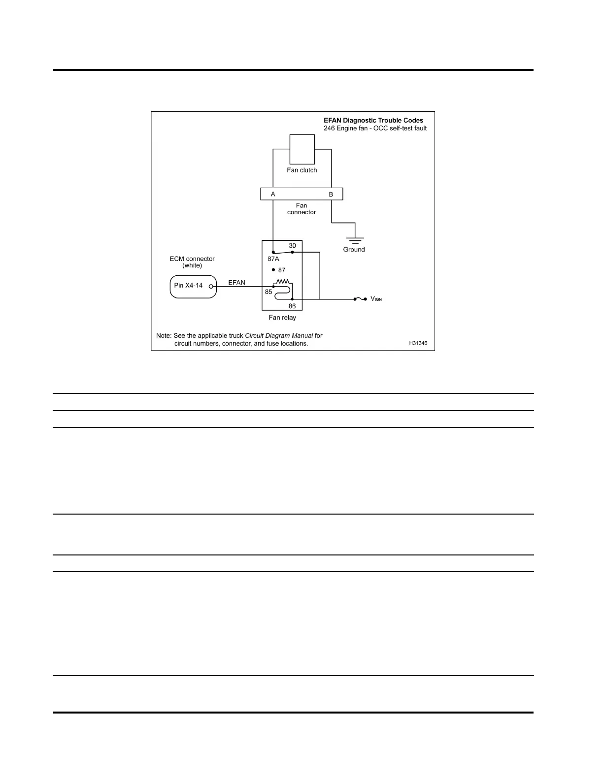
Figure 435 Fan clutch circuit diagram
Voltage Checks at Fan Connector (Disconnect fan connector. Turn the ignition switch to ON.)
Test Point
Spec Comment
KOEO
Atognd B+±0.5V
If < B+, check relay. Also check for an open circuit,
short to ground, or short to voltage source. Do Output
State Test - Voltage Check at Fan Connector.
B to gnd 0 V to 0.25 V
If > 0.25 V, check for an open ground circuit or a short to
voltage source. Do Harness Resistance Checks.
Output State Test - Voltage Check at Fan Connector (Disconnect fan connector. Turn the ignition switch
to ON. Run the Output State Tests. For help, see “Diagnostic Software Operation” in Section 3 (page 68) for
procedure to run the Low and High Output State Tests.)
Test State/Point Spec Comment
Output State Test - Low
A to gnd 0 V to 0.25 V
If > 0.25 V, che ck relay. Also check for sh ort t o voltage
source.
Output State Test - High
Atognd B+±0.5V
If < B+, check relay. Also check for an open circuit,
short to ground, or a short to voltage source. Do Output
State Test - Voltage Checks at Fan Relay.
EGES-270-1
Read all safety instructions in the "Safety Information" section of this manual before doing any procedures.
Follow all warnings, cautions, and notes.
© August 2008 Navistar, Inc.
 Loading...


