376 7 ELECTRONIC CONTROL SYSTEMS DIAGNOSTICS
ECM / IDM Pin -Po int Diagnostics
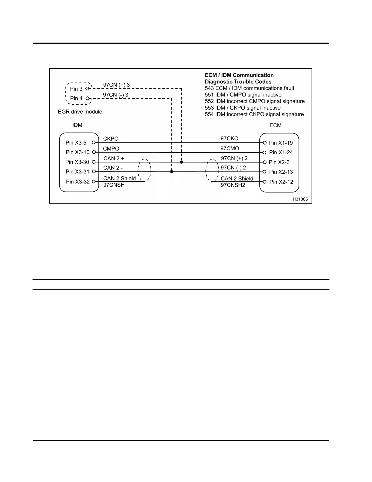
Figure 423 ECM / IDM circuit diagram
CAUTION: To avoid engine damage, turn the ignition switch to OFF before disconnecting the connector or
relay for the ECM and IDM. Failure to turn the switch to O FF will cause a voltage spike and damage to electrical
components.
ECM Connector Voltage Checks to Chassis Ground (Check with breakout box connected [X1 and X2]
to engine harness only. Inspect for bent pins or corrosion. Turn the ignition switch to ON. Note: ECM is
not connected. IDM output is checked through the wiring harness.)
Test Point
Spec Comment
X2–6 to gnd 1 V to 4 V
Digital signal. If no voltage check for open or short to ground
and do resistance checks to chassis ground, harness
resistance checks, and resistance checks - IDM CAN2
checks.
X2–13tognd 1Vto4V
Digital signal. If no voltage check for open or short to ground
and do resistance checks to chassis ground, harness
resistance checks, and resistance checks - IDM CAN2
checks.
X1–19tognd 11Vto12V
If < 11 V to 12 V, check for open or short to ground. Check
IDM power relay.
X1–24tognd 11Vto12V
If < 11 V to 12 V, check for open or short to ground. Check
IDM power relay.
X2–12tognd 0V
Ground, no voltage expected
EGES-270-1
Read all safety instructions in the "Safety Information" section of this manual before doing any procedures.
Follow all warnings, cautions, and notes.
© August 2008 Navistar, Inc.
 Loading...


