362 7 ELECTRONIC CONTROL SYSTEMS DIAGNOSTICS
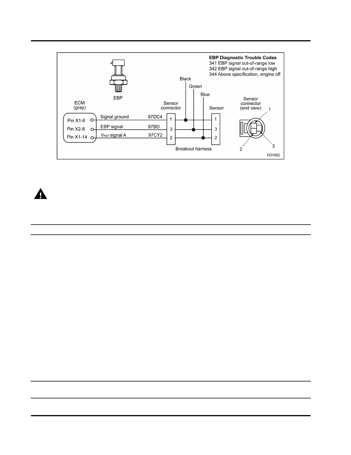
Figure 415 EBP circuit diagram
WARNING: To avoid serious personal injury, possible death, or damage to the engine or vehicle,
always disconnect main negative battery cable first. Always connect the main negative battery cable
last.
Circuit Checks for EBP Sensor (Use EST, DMM, breakout harness, and 500 Ohm Resistor Harness.)
Test Condition Spec Checks
Sensor disconnected using EST
0 V to 0.25 V
If > 0.25 V, check ground circuit for open or high
resistance, check signal ground for short to V
REF
or B+.
Voltage from Pin 2 (Blue) to ground
using DMM
5V±0.5V
If voltage > 5.5 V, check V
REF
for short to B+. If voltage
is < 4.5 V, check V
REF
circuit for open or short to ground.
500 Ohm Resistor Harness
connected between Pin 3 (Green)
and Pin 2 (Blue) of breakout
harness.
5V
If voltage < 4.9 V, check signal circuit for open or short
to ground.
— Disconnect connector 9260
1
. Measure resistance
from Pin 3 to Pin A of connector 9260 (spec > 1 kΩ)
to check for short to ground within wiring harness.
— Disconnect negative battery cable. Measure
resistance from Pin 3 to ground cable to check for
open in harness.
— Use a breakout box from Pin 3 to Pin X2–8 (spec <
5 Ω) to check for open in the harness.
Resistance from Pin 1 (Black) of
breakout harness to ECM chassis
ground Pin A of connector 9260
using DMM.
<5Ω If resistance is > 5 Ω, check for open or high resistance
between ECM and sensor connector. Use a breakout
box an d measure r esistance from between Pin 1 and
PinX1–6(spec<5Ω).
Connect engine harness to sensor. Use the EST to clear DTCs. If an active code remains after
checking test conditions, replace the EBP sensor.
EGES-270-1
Read all safety instructions in the "Safety Information" section of this manual before doing any procedures.
Follow all warnings, cautions, and notes.
© August 2008 Navistar, Inc.
 Loading...


