5 HARD START AND NO START DIAGNOSTICS 187
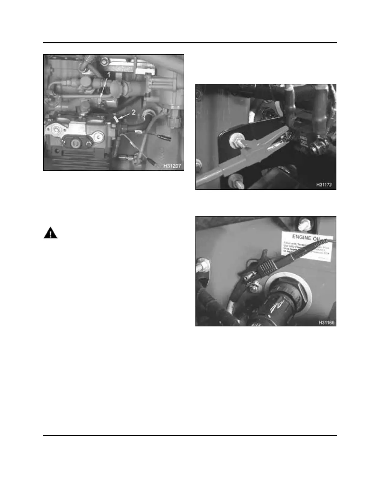
Figure 223 Actuator Breakout Harness to IP
R
1. IPR valve
2. Actuator Breakout Harness
Procedure
WARNING: To avoid serious personal inj
ury,
possible death, or damage to the engin
eor
vehicle, read all safety instructio
ns in the “Safety
Information” section of this manual
.
1. Disconnect engine wiring harnes
s connector from
IPR valve and inspect engine harn
ess terminals
and IPR valve for corrosion, ben
t pins, or pins
pushed back.
• If the harness connector or the I
PR valve is
corroded, replace the harness
connector and
IPR valve. Retest injection
control pressure.
• If pins are bent or pushed bac
k, repair as
necessary. Retest injecti
on control pressure.
• If the wiring harness connec
tor and the IPR
valve are not corroded or da
maged, continue
with step 2.
2. Connect Actuator Breako
ut Harness to IPR. Do
not connect engine harn
ess.
CAUTION: If the engine harness is connected to
the actuator breakout harness, the ignition s witch
fuse will blow or cause damage to wiring harness.
Figure 224 B+ on power distribution termi
nal
Figure 225 Ground to
terminal on cowl
3. Apply B+ volts an d g
round to the IPR valve.
EGES-270-1
Read all safety instructions in the "Safety Information" section of this manual before doing any procedures.
Follow all warnings, cautions, and notes.
©August 2008 Navistar, Inc.
 Loading...


