190 5 HARD START AND NO START DIAGNOSTICS
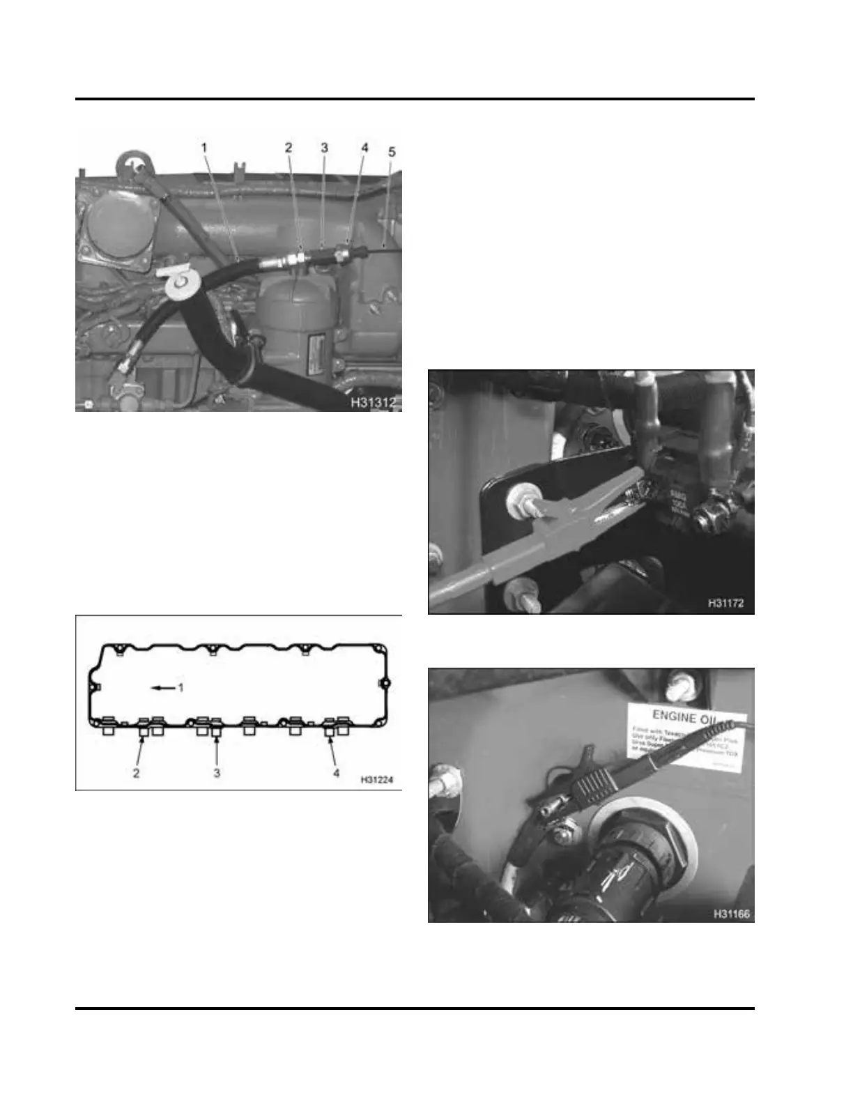
Figure 230 High-pressure oil hose, ICP Te
st Kit,
sensor, and Pressure Sensor Breakout Ha
rness
1. High-pressure hose
2. Fitting, 13/16-16 NPT
3. ICP sen sor adapter
4. ICP sensor
5. VC Gasket Bre akout Harness
3. Install test hose assembly to high-pre
ssure pump.
Figure 231 Valve cover gasket
1. Frontofengine
2. Pass-th rough connector for BCP sensor
3. Pass-through connector for brake shut-off valve
4. Pass-through connector for ICP sensor
4. Disconnect engine wiring harness from valve
cover gasket (ICP connector).
5. Connect VC Gasket B reakout Harness between
high-pressure hose assembly and engine wiring
harness only.
NOTE: If connected to the valve cover, gasket
connector – readings will be wrong, because the
harness w ill be connected to the ICP sensor under
the valve cover.
6. Connect Actuator Breakout Harness to IPR. Do
not connect engine harness.
CAUTION: If the eng ine h arne ss is co nnected to
the actuator breakout harness, the ignition switch
fuse will blow or cause damage to wiring harness.
Figure 232 B+ on power distribu
tion terminal
Figure 233 G round to terminal on cowl
7. Apply B+ volts and ground to the IPR valve.
EGES-270-1
Read all safety instructions in the "Safety Information" section of this manual before doing any proced ures.
Follow all warnings, cautions, and notes.
©August 2008 Navistar, Inc.
 Loading...


