6 PERFORMANCE DIAGNOSTICS 237
NOTE: BCP value should be 0 psi. However,
BCP values may fluctuate as much as 345 kPa
(50 psi). Electromagnetic Interference (EMI) or
ground shift can cause an insignificant voltage
shift that does not indicate a problem.
5. Run engine at high idle, monitor ICP, and record
initial results on Diagnostic Form. Continue to
run the engine at high idle for 2 minutes, monitor
ICP, and record the 2 minute results on Diagnostic
Form. Compare the two ICP readings. ICP that
rises above the specification at any point during
the two minutes, indic at es oil aeration.
• If ICP is high or unstable for low or high idle,
do step 6.
• If BCP is above zero when engine brake is
inactive, diagnose BCP sensor, c ircuit, and
engine brake components.
•IfICPistospecifi cation, continue with Test 11
Injector Disable.
WARNING: To avoid serious personal inju
ry,
possible death or damage to the engine or
vehicle
– comply with the following when taking
oil
sample:
• When routing oil line, do not run the lin
etoo
close to moving parts.
• Do not let the line touch hot engine s
urfaces.
• Oil is hot. Use protective gloves wh
en taking
oil sample. Use caution handling o
il sample to
avoid spilling.
WARNING: To avoid serious personal injury
or possible death, do not allow engine fluids to
stay on your skin. Clean your skin and nails
with soap and water, or a good hand cleaner.
Wash or properly throw away clothing or rags
containing engine fluids. Engine fluids contain
certain elements that may be unhealthy for skin
and could even cause cancer.
NOTE: Engine fluids, oil, fuel, and coolant, can be a
threat to the environment. Never dispose of engine
fluids by putting them in the trash, pouring them on the
ground, in the sewers, in streams or bodies of water.
Collect and dispose of engine fl uids according to local
regulations.
6. Turn off engine.
7. Use the ICP system test adapter and inline
shut-offvalvetomakeatestlineassemblyto
take oil sample.
NOTE: The mechanic is expected to ke ep the
test line for future diagnostics. Expense the test
line as an essential tool and keep it with other
diagnostic tools. Warranty will not cover the cost
of the test line.
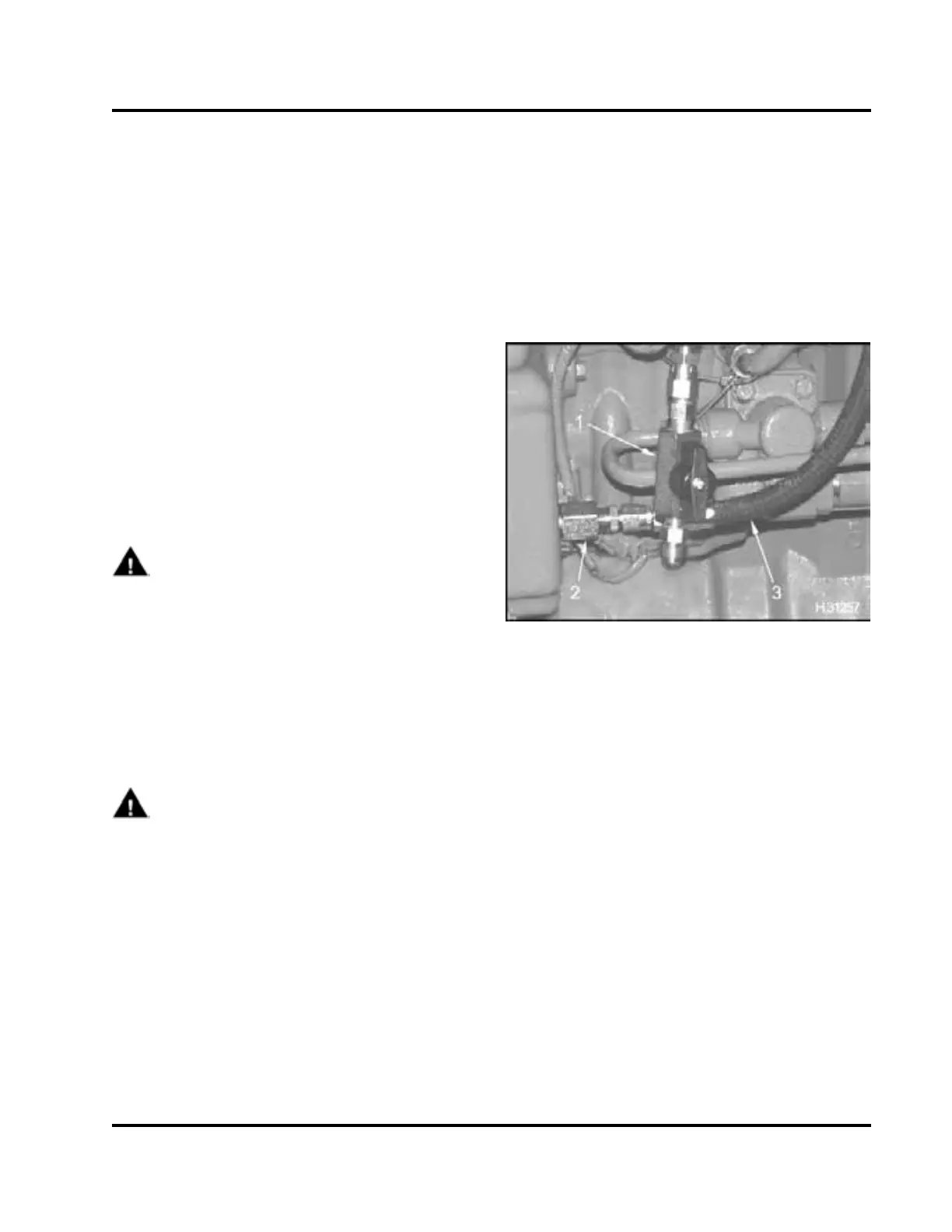
Figure 309 Test line assembly installed
1. Inline shut-off valve
2. ICP system test adapter
3. Oil sample line
8. Remove EOT sensor from EOT port. Oil will spill
out. Quickly install test line assembly.
9. Run engine at high idle for 2 minutes.
10. Return engine to low idle, take oil sample, and
check for aerated oil.
11. Record results on Diagnostic Form.
• If oil is aerated, a large quantity of air bubbles
mixed throughout the oil, or foam build up on
top of the oil will be seen. Correct condition.
• If oil is not aerated, disconnect ICP sensor
and check engine stability. If problem is
corrected, see “ICP Operational Voltage
Checks” in Section 7.
EGES-270-1
Read all safety instructions in the "Safety Information" section of this manual before doing any procedures.
Follow all warnings, cautions, and notes.
©August 2008 Navistar, Inc.
 Loading...


