240 6 PERFORMANCE DIAGNOSTICS
6. Run engine at low idle, measure ICP signal
voltage, and record on Diagnostic Form.
• If ICP is high or unstable for low or high idle,
do step 8.
• If IC P is in spec ification, continue with Test 11
Injector Disable.
7. Run engine at high idle, monitor ICP, and record
initial results on Diagnostic Form. Continue to
run the engine at high idle for 2 minutes, monitor
ICP, and record the 2 minute results on Diagnostic
Form. Compare the two ICP readings. ICP that
rises above the specification at any point during
the two minutes, indicates oil aeration.
• If ICP is high or unstable for low or high idle,
do step 8.
• If IC P is in spec ification, continue with Test 11
Injector Disable.
WARNING: To avoid serious personal injury,
possible death or damage to the engine or ve
hicle
– comply with the following when taking oi
l
sample:
• When routing oil line, do not run the line t
oo
close to moving parts.
• Do not let the line touch hot engine surfac
es.
• Oil is hot. Use protective gloves when
taking
oil sample. Use caution handling oil s
ample to
avoid spilling.
WARNING: To avoid serious personal injury
or possible death, do not allow engine fluids to
stay on your skin. Clean your skin and nails
with soap and water, or a good hand cleaner.
Wash or properly throw away clothing or rags
containing engine fluids. Engine fluids contain
certain elements that may be unhealthy for skin
and could even cause cancer.
NOTE: Engine fluids, oil, fuel, and coolant, can be a
threat to the environment. Never dispose of engine
fluids by putting them in the trash, pouring them on the
ground, in the sewers, in streams or bodies of water.
Collect and dispose of engine fluids according to local
regulations.
8. Turn off engine.
9. Use the ICP system test adapter and inlin e
shut-off valve to make a test line assembly to
take oil sample.
NOTE: The mechanic is expected to keep the
test line for future diagnostics. Expense the test
line as an essential tool and keep it with other
diagnostic tools. Warranty will not cover the cost
of the test line.
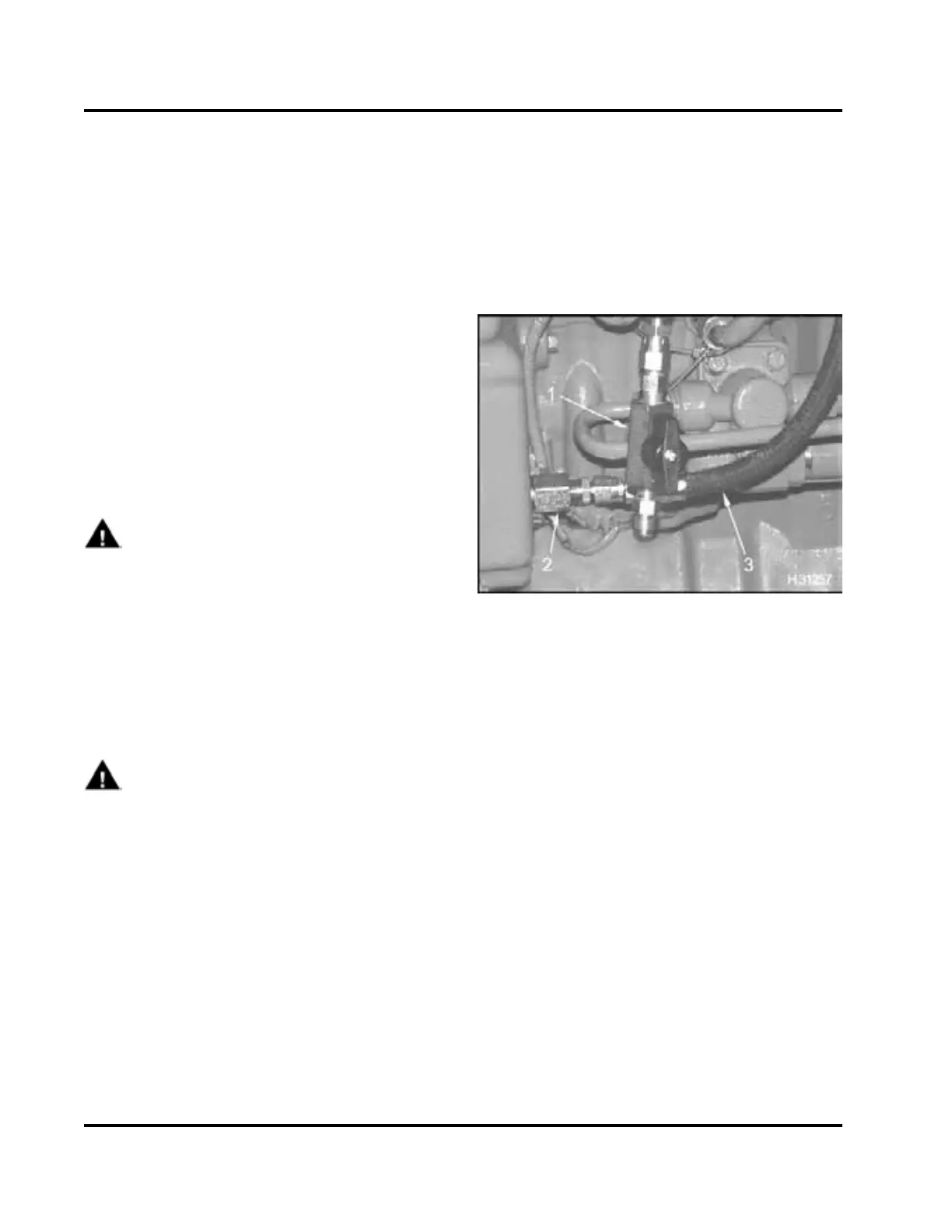
Figure 312 Test hose assembly
1. Inline shut-off valve
2. ICP system test adapter
3. Oil sample line
10. Remov e EOT sensor fro m EOT port. Oilwillspill
out. Quickly install test hose assembly and
capture oil sample in clear container.
11. Run engine at high idle for 2 minutes.
12. Return engine to low idle, take oil sample, and
check for aerated oil.
13. Record results on Diagnostic F orm.
• If oil is aerated, a large quantity of air bubbles
mixed throughout the oil, or foam build up on
top of the oil will be seen. Correct condition.
• If oil is not aerated, disconnect ICP sensor
and check engine stability. If proble m is
corrected, see “ICP Operational Volta g e
Checks” – Section 7 (page 457).
• If ICP is still high or unstable, and engine has
optionalengine brake, continue to “Monitoring
BCP u sin g VC G a ske t Break ou t H arness.”
EGES-270-1
Read all safety instructions in the "Safety Information" section of this manual before doing any proced ures.
Follow all warnings, cautions, and notes.
©August 2008 Navistar, Inc.
 Loading...


