260 6 PERFORMANCE DIAGNOSTICS
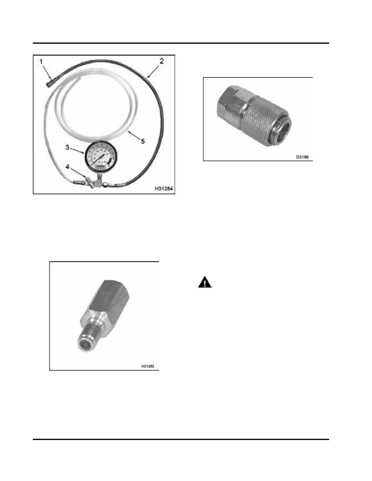
Figure 341 Fuel Pressure Gauge
1. Quick disconnect check valve
2. Fuel test line
3. Fuel Pressure Gauge
4. Inline shut-off valve
5. Clear test line
Figure 342 Fuel Pressure Test Adapter
NOTE: If the engine is equipped with a Shrader valve,
use the Fuel Pre ssure Test Adapter.
Figure 343 Fuel/Oil Pressure Test C oupler
NOTE: If the engine is equipped with a diagnostic
coupling, adapt the Fuel/Oil Pressure Test Coupler to
the Fuel Pressure Gauge.
3. Connect the Fuel Pressure Gauge and shut-off
valve to the inta ke manifold fuel pressure test po rt.
NOTE: Breaking any fuel system joint will induce
air into the fuel system. The air should p ass in a
short period of time.
4. Mount the Fuel Pressure Gauge where it can be
seen from the drivers seat.
WARNING: To avoid serious personal
injury, possible death or damage to the engine
or vehicle – comply with the following:
When routing test line, do not crimp the line,
run the line too close to moving parts, or let
the line touch hot engine surfaces. Secure
thegaugeandtestlineinthecabsoasnot
to obstruct the operator.
EGES-270-1
Read all safety instructions in the "Safety Information" section of this manual before doing any proced ures.
Follow all warnings, cautions, and notes.
©August 2008 Navistar, Inc.
 Loading...


