276 6 PERFORMANCE DIAGNOSTICS
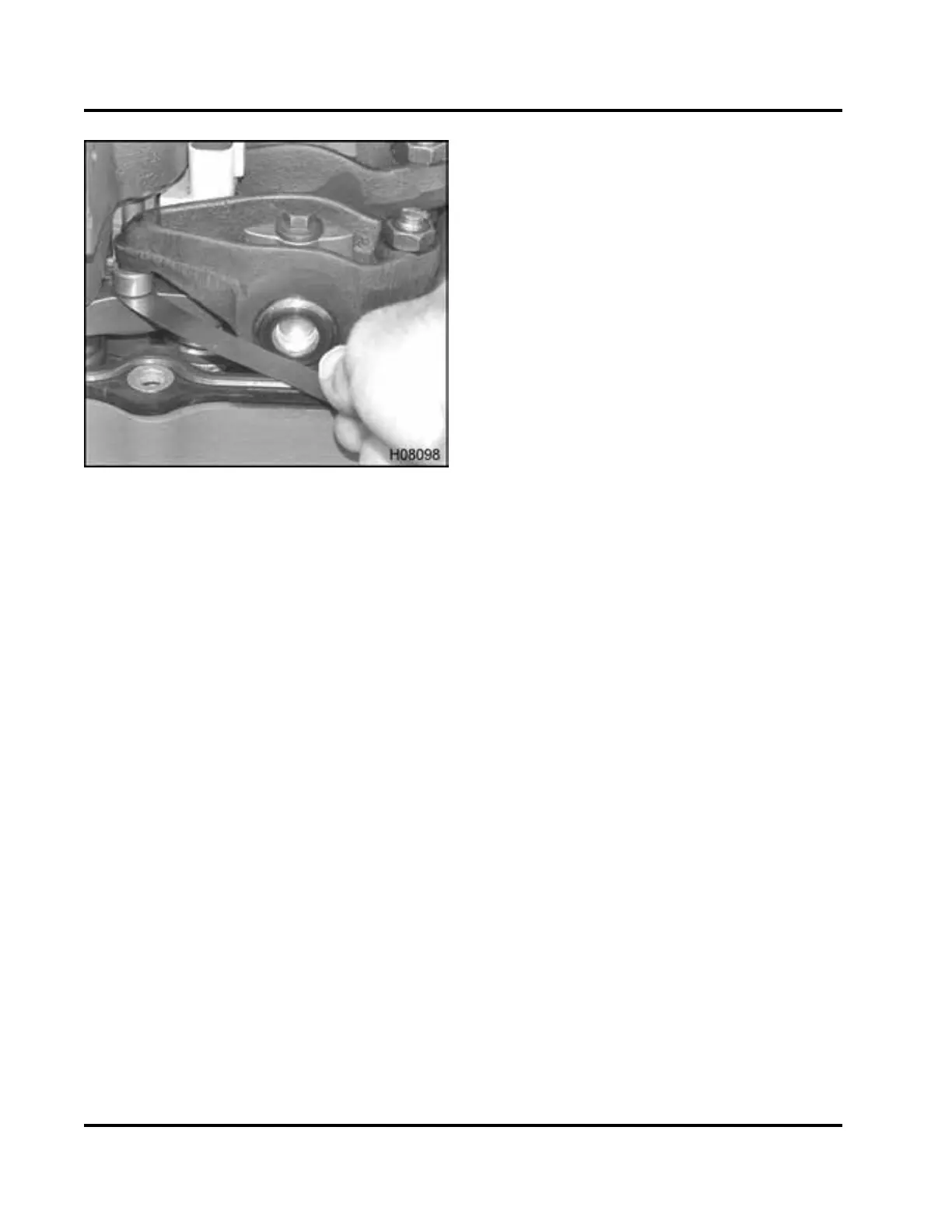
Figure 360 Feeler gauge between the pivot foot
and valve bridge
4. Check cold valve lash with a (0.019 in) feeler
gauge between the pivot foot and valve bridge.
If adjustment is required, loosen the locknut and
turn the valve adjustment screw until a light drag
is felt.
5. Once valve adjustment is set, tighten the locknut
to 27 N·m (20 lbf·ft) and remove the feeler gauge.
Recheck for light drag on feeler gauge . If drag is
too tight or loose, repeat steps 4 and 5.
If engine is equipped with the Diamond Logic®
engine brake, co rre s p onding brake actuator lash
can be adjusted before rotating the cra nk s h aft.
See “Brake Actu at or Lash” in this section .
6. Turn crankshaft 360° in the d irection of engine
rotation to remove gear lash from gear train and
realign the timing mark on the damper pulley with
the TDC ma rk on the fr ont cover.
•Iffirst adjustments were with piston 1 at T DC
compression, cylinder 6 should be at TDC
compression. Confirm that valves are closed
by making sure that push rods for cylinder 6
are loose and turn easily. If piston 6 is at TDC
compression, see and do steps 4 and 5.
•Iffirst adjustments were with piston 6 at T DC
compression, cylinder 1 should be at TDC
compression. Confirm that valves are closed
by making sure that push rods for cylinder 1
are loose and turn easily. If piston 1 is at TDC
compression, see and do steps 4 and 5.
Before doing step 7, If engine is equipped with
the Diamond Logic® engine brake corresponding
brake actuator lash can be adjusted. See “Brake
Actuator Lash” in this section.
7. Install valve cover following procedure in Engine
Service Manual.
EGES-270-1
Read all safety instructions in the "Safety Information" section of this manual before doing any proced ures.
Follow all warnings, cautions, and notes.
©August 2008 Navistar, Inc.
 Loading...


