286 7 ELECTRONIC CONTROL SYSTEMS DIAGNOSTICS
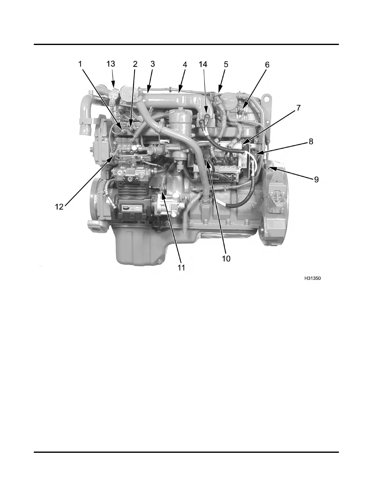
Figure 365 Sensor location – Left View
1. Manifold Absolute Pressure
(MAP) se nsor
2. Manifold Air Temperature (MAT)
sensor
3. Optional Brake Control Pressure
(BCP) sensor (under valve
cover)
4. Optional Brake Shut-off Valve
(under valve cover)
5. Injection Control Pressure (ICP)
sensor (under valve cover)
6. Valve cover gasket pass-through
connector
a. (6) four-wire connectors for
fuel injectors
b. (1) three-wire connector for
ICP sensor
c. Engine brake application
– (1) th ree-wire connector
for the BCP se nso r a nd (1)
three-wire connector for the
brake shut-off valve.
7. Electronic Control Mod ule (ECM)
and Injector Drive Module (IDM)
assembly
8. Inlet A ir Heater (IAH) relays
9. Crankshaft Position (CKP)
sensor
10. Exhaust Gas Recirculation
(EGR) drive module
11. Engine Oil Pressure (EOP)
sensor
12. Engine Oil Temperature (EOT)
sensor
13. Exhaust Gas Recirculation
(EGR) valve
14. Inlet Air Heater (IAH) elements
NOTE: For Water in F uel (WIF) sensor and option al
Engine Fuel Pressure (EFP) sensor location, see
“Fuel Flow” in Section 1 (page 35).
EGES-270-1
Read all safety instructions in the "Safety Information" section of this manual before doing any procedures.
Follow all warnings, cautions, and notes.
© August 2008 Navistar, Inc.
 Loading...


