342 7 ELECTRONIC CONTROL SYSTEMS DIAGNOSTICS
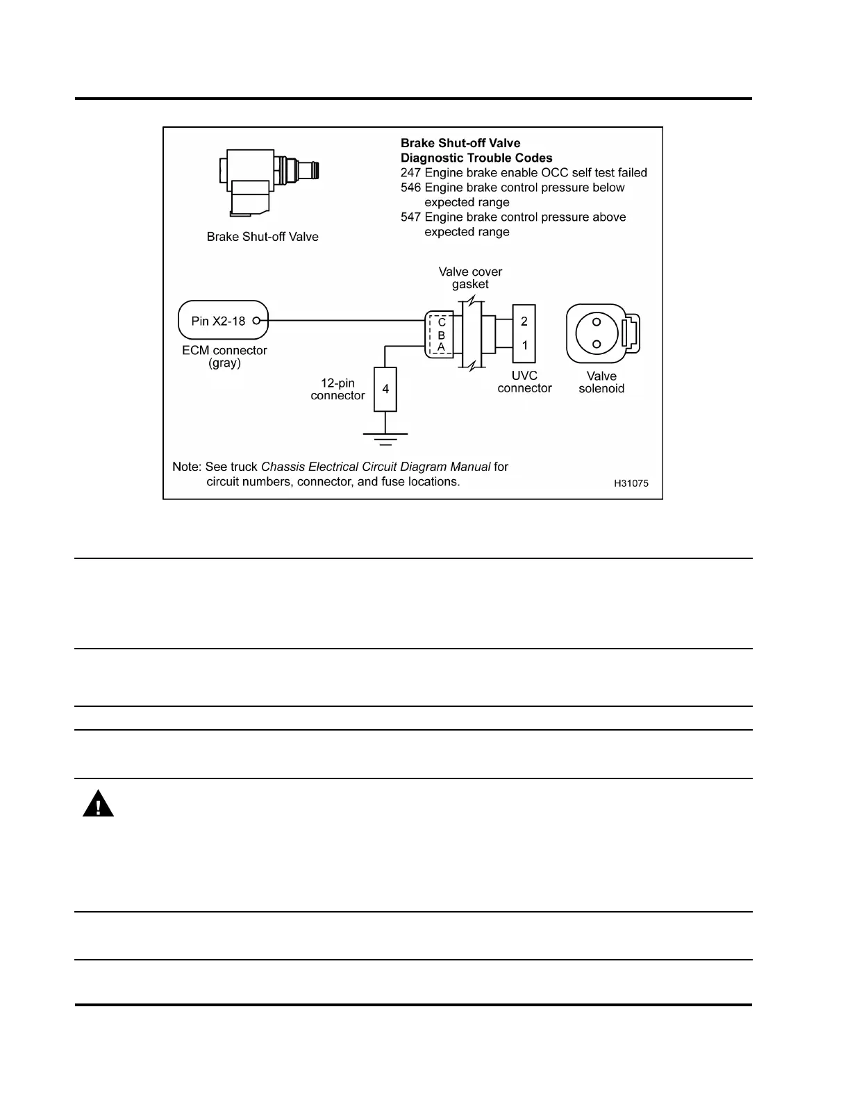
Figure 400 Brake S hut-off Valve c
ircuit diagram
NOTE: Complete all pin-point dia
gnostics (ECM to valve cover gasket connector) before removing
valve cover for under-valve-co
ver diagnostics.
• Turn the ignition switch to OF
F before disconnecting engine wiring h arness connectors from components.
• See truck Chassis Electrical
Circuit Diagram Manual for circuit numbers, connector and fuse locations.
Harness Resistance Check – Valve Cover Gasket Connector to ECM Chassis Ground (Turn the
ignition switch to OFF. Disconnect chassis connector 9260
1
. Connect VC G asket Breakout Harness to
engine wiring harness only.)
Test Point
Spec Commen t
AtoPinA(9260) <5Ω If > 5 Ω, check for an open
circuit.
C to Pin A (9260) > 1 kΩ If < 1 kΩ, check for short to ground within wiring harness.
WARNING: To avoid serious personal injury, possible death, or damage to the engine or vehicle,
always disconnect main negative battery cable first. Always connect the main negative battery cable
last.
Harness Resistance Check – Valve Cover Gasket Connector to Chassis Ground (Turn the ignition
switch to OFF. Disconnect chassis connector 9260
1
. Disconnect negative battery cable. Disconnect harness
from valve cover gasket. Use disconnected negative battery cable for ground test point.)
A to gnd cable
>500Ω If < 500 Ω,checkfo
r short to ground.
C to gnd cable > 1 kΩ If < 1 kΩ, check for short to ground.
EGES-270-1
Read all safety instructions in the "Safety Information" section of this manual before doing any procedures.
Follow all warnings, cautions, and notes.
© August 2008 Navistar, Inc.
 Loading...


