7 ELECTRONIC CONTROL SYSTEMS DIAGNOSTICS 397
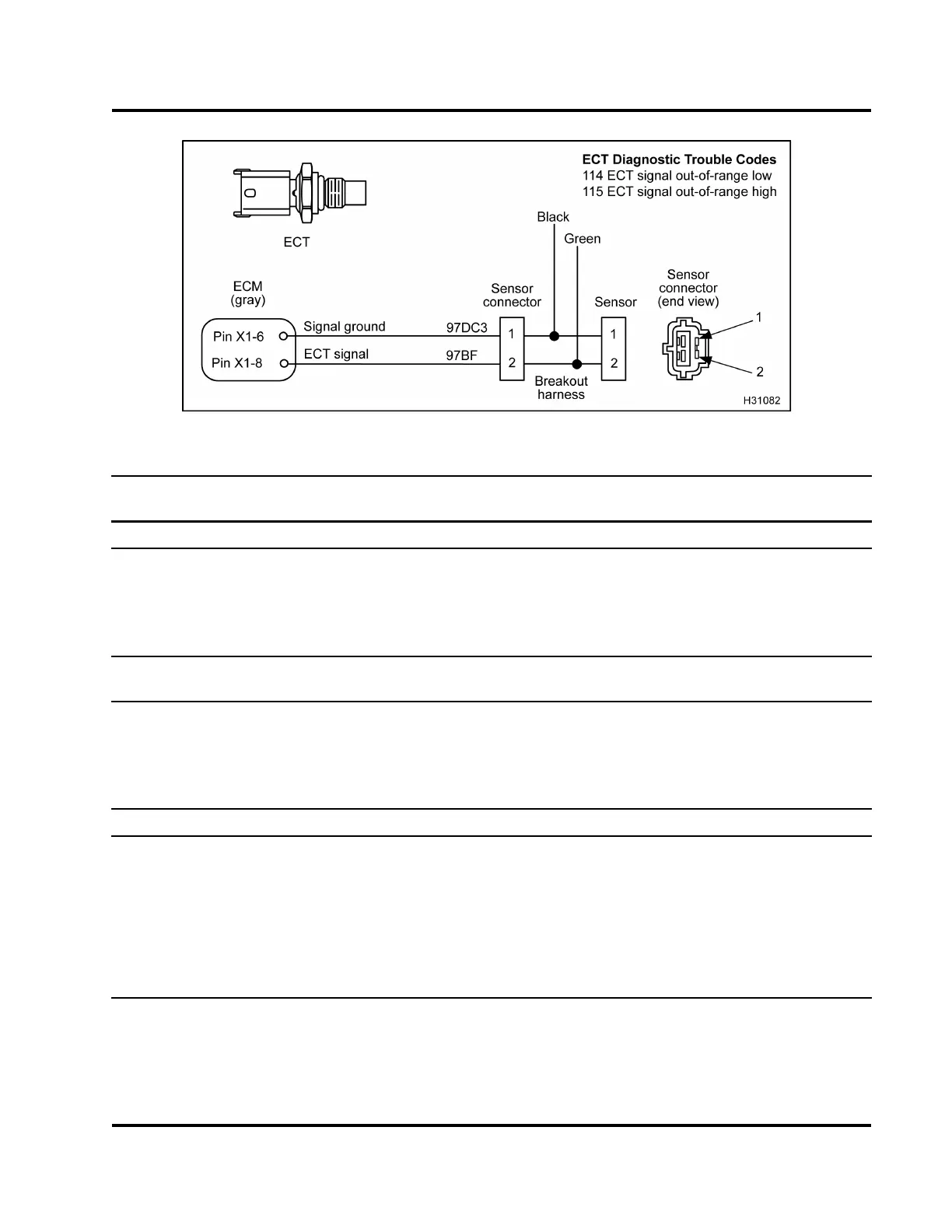
Figure 432 ECT circuit diagram
Operational Voltage Checks for ECT Sensor with Breakout Harness (Check with breakout harness
connected to sensor and engine harness.)
Test Point
Coolant Temp
Resistance Voltage
2 (Green) to 1 (Black) 108 °C (228 °F) 1.605 kΩ
0.37 V
2 (Green) to 1 (Black) 87.7 °C (190 °F) 3 kΩ
0.65 V
2 (Green) to 1 (Black) 0 °C (32 °F) 91.1 kΩ
3.86 V
2 (Green) to 1 (Black) –17.8 °C (0 °F) 208 kΩ
4.25 V
Operational Voltage Checks for ECT Sensor with Breakout Box (Check with breakout box connected
[X-1 only] to ECM and engine harness.)
X1–8 to X1–6
108 °C (228 °F) 1.605 kΩ
0.37 V
X1–8 to X1–6
87.7 °C (190 °F) 3 kΩ
0.65 V
X1–8 to X1–6
0 °C (32 °F) 91.1 kΩ
3.86 V
X1–8 to X1–6
–17.8 °C (0 °F) 208 kΩ
4.25 V
ECT Diagnostic Trouble Codes
DTC 114 = Signal voltage was < 0.127 V for more than 0.35 second.
DTC 115 = Signal voltage was > 4.6 V for more than 0.35 second.
DTC 316 = See “Engine Warning and Protection System” (page 440).
DTC 321 = See “Engine Warning and Protection System” (page 440).
DTC 322 = See “Engine Warning and Protection System” (page 440).
DTC 325 = See “Engine Warning and Protection System” (page 440).
EGES-270-1
Read all safety instructions in the "Safety Information" section of this manual before doing any procedures.
Follow all warnings, cautions, and notes.
© August 2008 Navistar, Inc.
 Loading...


