7 ELECTRONIC CONTROL SYSTEMS DIAGNOSTICS 467
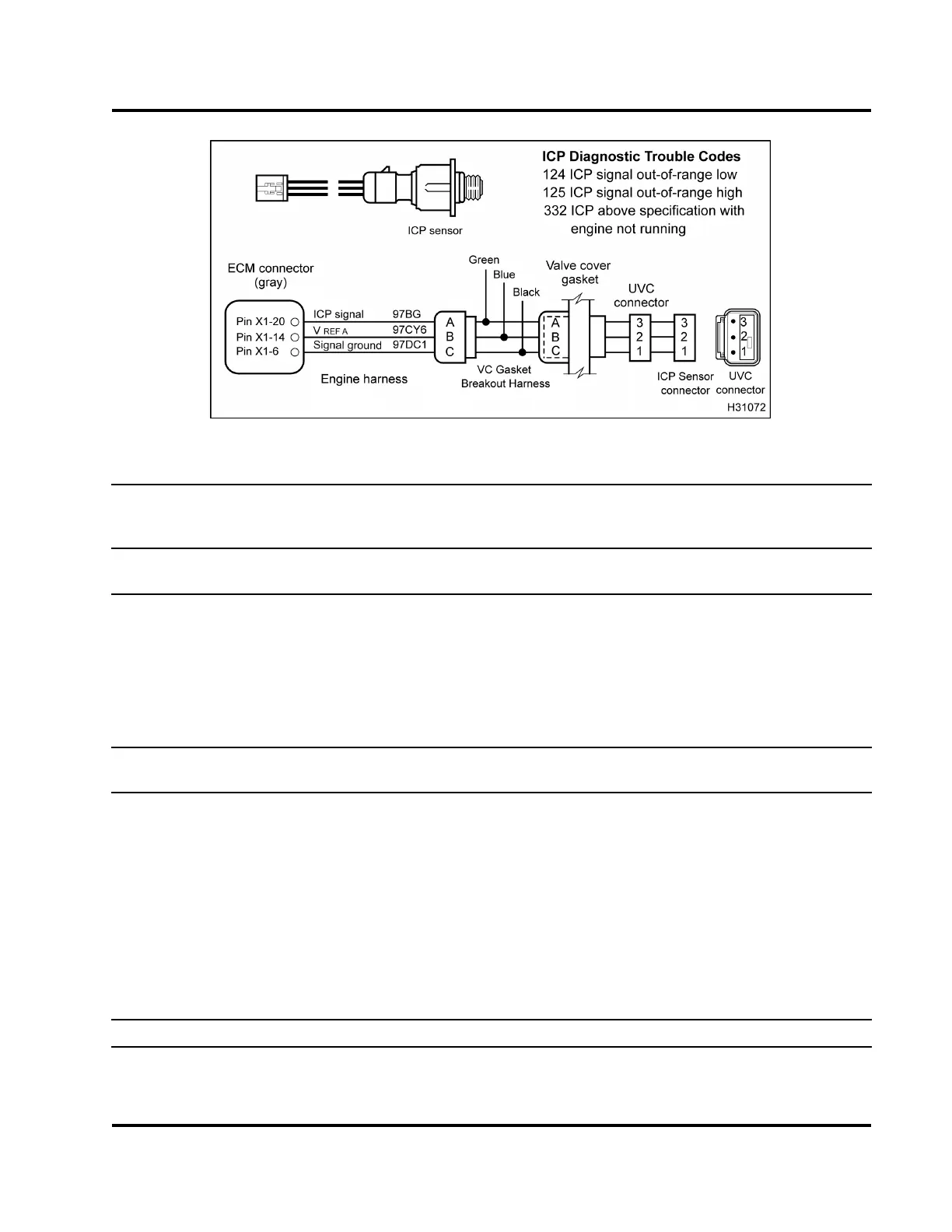
Figure 468 ICP circuit diagram with VC Gaske
t Breakout Harness
Operational Voltage Checks for ICP Sensor
with VC Gasket B reakout Harness (These checks are done
if an EST is not a vailable and the valve cove
r is not remove d. Check with VC Gasket Breakout H arness
connected to valve cover gasket connecto
r and engine harness.)
Test Point
EST voltage readings:
Signal to ground
Spec Checks
AtoC
0.15 V to 0.3 V
0kPa(0psi)
Atmospheric pressure with key-on
engine-off
A to C See Performance Specifications.
Minimum at engine cranking speed
A to C See Performance Specifications.
Low idle, no load
A to C See Performance Specificatio
ns.
High idle, no load
A to C See Performance Specifications. Rated speed, full load
Operational Voltage Checks for ICP Sensor with Breakout Box (Check with breakout box [X -1]
connected to ECM and engine harness.)
X1–20 to
X1–6
0.15 V to 0.3 V
0kPa(0psi)
Atmospheric pressure with key-on
engine-off
X1–20 to
X1–6
See Performance Specifications.
Minimum at engine cranki
ng speed
X1–20 to
X1–6
See Performance Specifications.
Low idle, no load
X1–20 to
X1–6
See Performance Spec
ifications.
High idle, no load
X1–20 to
X1–6
See Performance Specifications. Rated speed, full load
ICP Diagnostic Trouble Codes
DTC 124 = Signal voltage was < 0.039 V for m ore tha n 0.1 second
EGES-270-1
Read all safety instructions in the "Safety Information" section of this manual before doing any procedures.
Follow all warnings, cautions, and notes.
© August 2008 Navistar, Inc.
 Loading...


