7 ELECTRONIC CONTROL SYSTEMS DIAGNOSTICS 491
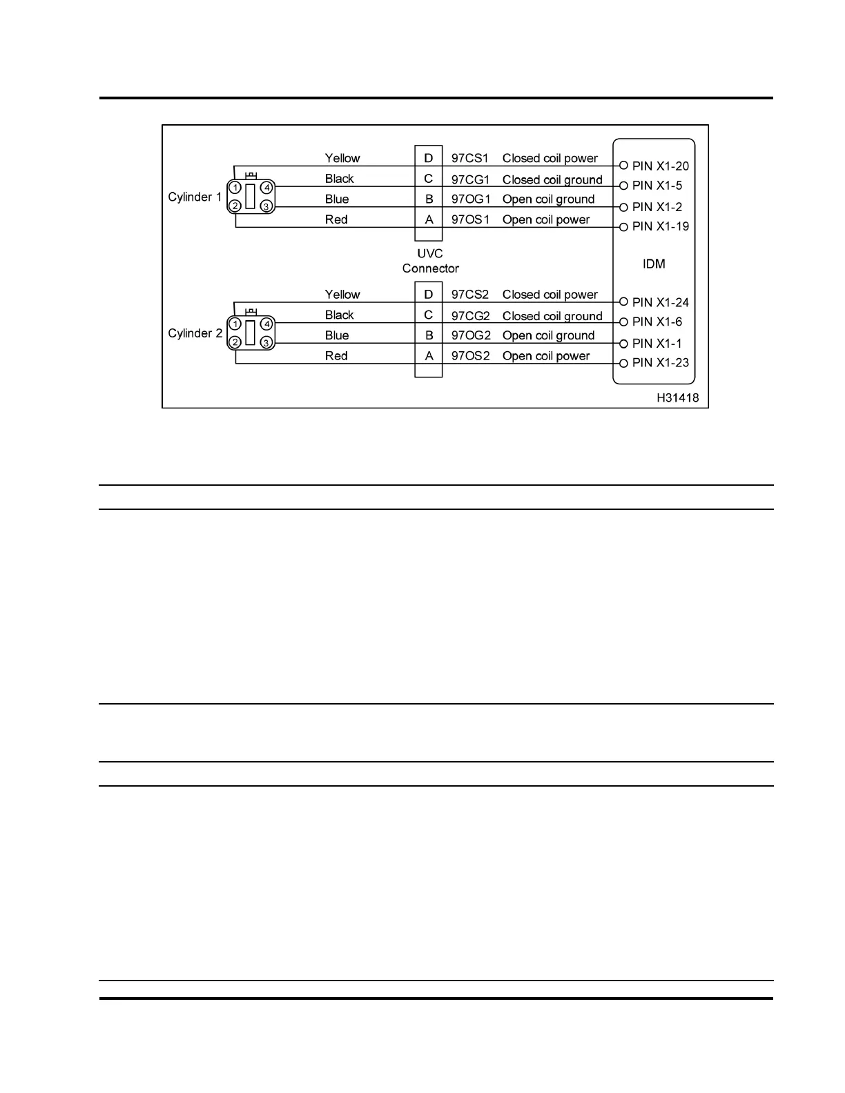
Figure 477 Cylinder 1 and 2 circuit diagram
Injector Cy linder 1
Test Point
Spec Comment
X1–2 to X1–19
0.7 Ω to 1.5 Ω If > 1.5 Ω, check for open or high resistance between IDM
and injector, or open injector coil
X1–2 to gnd, X1–19 to gnd
>1kΩ If < 1 kΩ, check for short to ground in harness or injector
coil. Disconnect injector and retest. If > 1 kΩ, the short
is in the injector.
X1–5 to X1–20
0.7 Ω to 1.5 Ω If > 1.5 Ω, check for open or high resistance between IDM
and injector, or open injector coil.
X1–5 to gnd, X1–20 to gnd
>1kΩ If < 1 kΩ, check for short to ground in harness or injector
coil. Disconnect injector and retest. If > 1 kΩ, the short
is in the injector.
Injector Cy linder 2
Test Point
Spec Comment
X1–1 to X1–23
0.7 Ω to 1.5 Ω If > 1.5 Ω, check for open or high resistance between IDM
and injector, or open injector coil
X1–1 to gnd, X1–23 to gnd
>1kΩ If < 1 kΩ, check for short to ground in harness or injector
coil. Disconnect injector a nd retest. If > 1 kΩ,theshort
is in the injector.
X1–6 to X1–24
0.7 Ω to 1.5 Ω If > 1.5 Ω, check for open or high resistance between IDM
and injector, or open injector coil
X1–6 to gnd, X1–29 to gnd
>1kΩ If < 1 kΩ, check for short to ground in harness or injector
coil. Disconnect injector a nd retest. If > 1 kΩ,theshort
is in the injector.
EGES-270-1
Read all safety instructions in the "Safety Information" section of this manual before doing any procedures.
Follow all warnings, cautions, and notes.
© August 2008 Navistar, Inc.
 Loading...


