506 7 ELECTRONIC CONTROL SYSTEMS DIAGNOSTICS
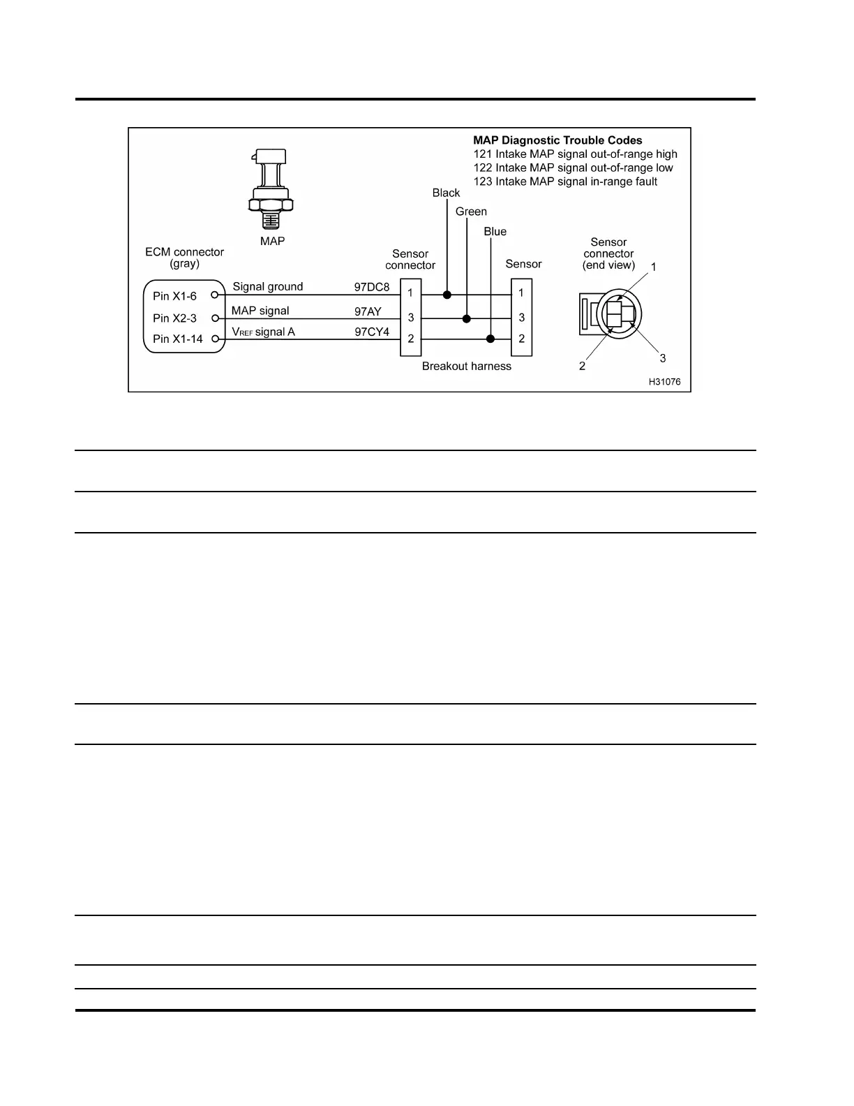
Figure 487 MAP circuit diagram
Operational Voltage Checks for MAP Sensor with Breakout Harness (Check with breakout harness
connected to sensor and engine harness.)
Test Point
EST voltage readings:
Signal to ground
Spec Comment
3(Green)to1(Black)
0.92 V
0 kPa (psi) Vo lta ge with key-on engine-off.
Atmospheric pressure dependent
on altitude and BAP pressure.
3(Green)to1(Black)
1.73 V
55kPa(8psi)
3(Green)to1(Black)
2.72 V
129 kPa (18 psi)
3(Green)to1(Black)
3.71 V
193 kPa (28 psi)
3 (Green) to 1 (Black) See appropriate performance specification
below.
Rated speed, full load
Operational Voltage Checks for MAP Sensor with Breakout Box (Check with breakout box connected
[X1 and X2 only] to the ECM and engine harness.)
X2–3 to X1–6 0.92 V
0 k Pa (psi) Voltage with key-on en
gine-off.
Atmospheric pressur
e dependent
on altitude and BAP pr
essure.
X2–3 to X1–6 1.73 V
55kPa(8psi)
X2–3 to X1–6 2.72 V
129 kPa (18 psi)
X2–3 to X1–6 3.71 V
193 kPa (28 psi)
X2–3 to X1–6
See appropriate performance specification
below.
Rated speed, full load
“DT 466 Performance Specifications” – Appendix A (page 595)
“DT 570 and HT 570 Performance Specifications – Appendix B (page 619)
MAP Diagnosti
c Trouble Codes
EGES-270-1
Read all safety instructions in the "Safety Information" section of this manual before doing any procedures.
Follow all warnings, cautions, and notes.
© August 2008 Navistar, Inc.
 Loading...


