48 1 ENGINE SYSTEMS
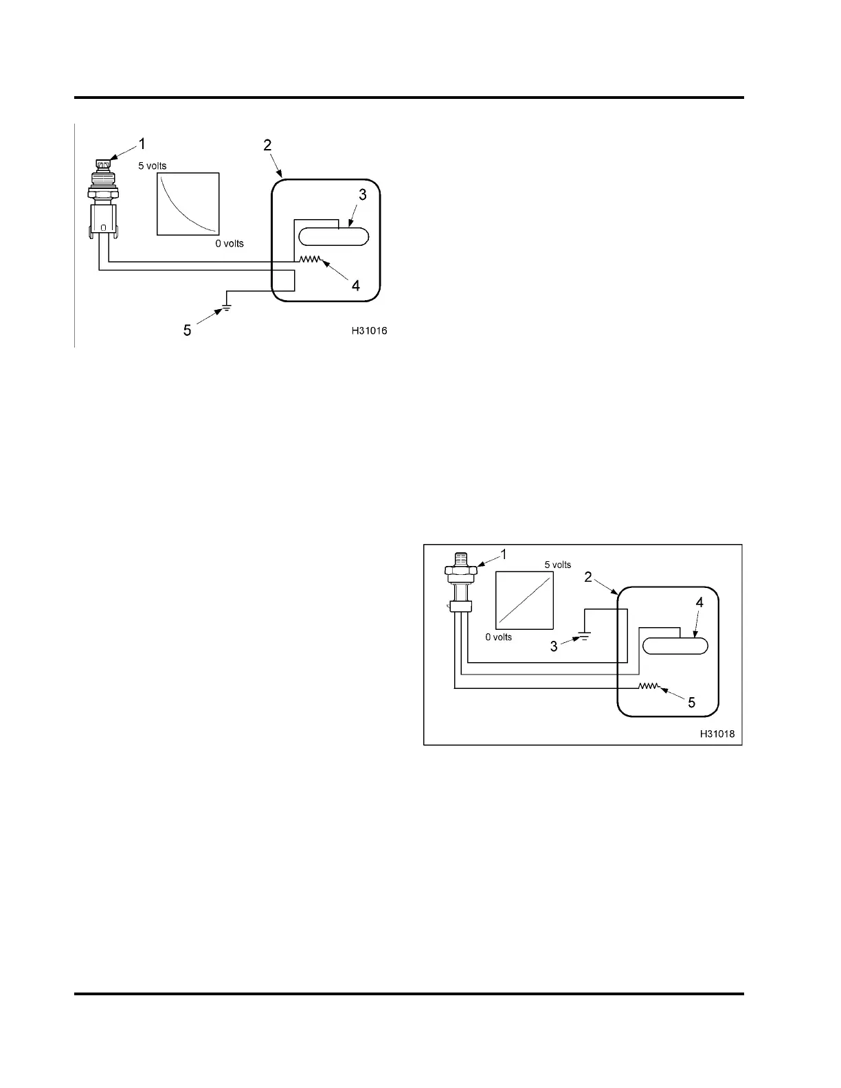
Figure 39 Thermistor
1. Temperature sensor
2. Electronic Control Modu le (ECM)
3. Microprocessor
4. Voltage reference (V
REF
)
5. Gr ound
Thermistors
•ECT
•EOT
•IAT
•MAT
A thermistor sensor changes its electrical resistance
with changes in temperature. Resistance in the
thermistor decreases as temperature increases, and
increases as temperature decreases. Thermistors
work with a resistor t ha t limits current in the ECM to
form a voltage signal matched with a temperature
value.
The top half o f the vo ltage divide r is the current limiting
resistor inside the ECM. A thermistor sensor has two
electrical connectors, signal return and ground. The
output of a thermistor sensor is a nonlinear analog
signal.
Engine Coolant Temperature (ECT)
The ECM monitors the ECT signal and uses this
information for the instrument panel temperature
gauge, coolant compensation, Engine Warning
Protection System (EWPS), and inlet air heater
operation. The ECT is a backup, if the EOT is
out-of-range. The ECT sensor is installed in the water
supply housing (Freon® compressor bracket), right of
the flat idle r pulley assembly.
Engine Oil Temperature (EOT)
The ECM monitors the EOT signal to control fuel
quantity and timing when operating the engine. The
EOT signal allows the ECM and IDM to compensate
for differences in oil viscosity for te mperature
changes. This ensures that power and torque
are available for all operating conditions. The EOT
sensor is installed in the re ar o f the front cover, left of
the high-pressure oil pump assembly.
Intake Air Temperature (IAT)
The ECM monitors the IAT signal to control timing and
fuel rate during cold starts. The IAT sensor is chassis
mounted on the air filter housing.
Manifold Air Temperature (MAT)
The ECM monitors the MAT signal for EGR operation.
The MAT sensor is installed right of the MAP sensor
in the intake m anifold.
Figure 40 Variable capacitance sensor
1. Pressure sensor
2. Electronic Control Mo dule (ECM)
3. Gr ound
4. Microprocessor
5. Voltage reference (V
REF
)
Variable Capacitance Sensors
• BAP
•MAP
• EBP
EGES-270-1
Read all safety instructions in the "Safety Information" section of this manual before doing any procedures.
Follow all warnings, cautions, and notes.
© August 2008 Navistar, Inc.
 Loading...


