534 7 ELECTRONIC CONTROL SYSTEMS DIAGNOSTICS
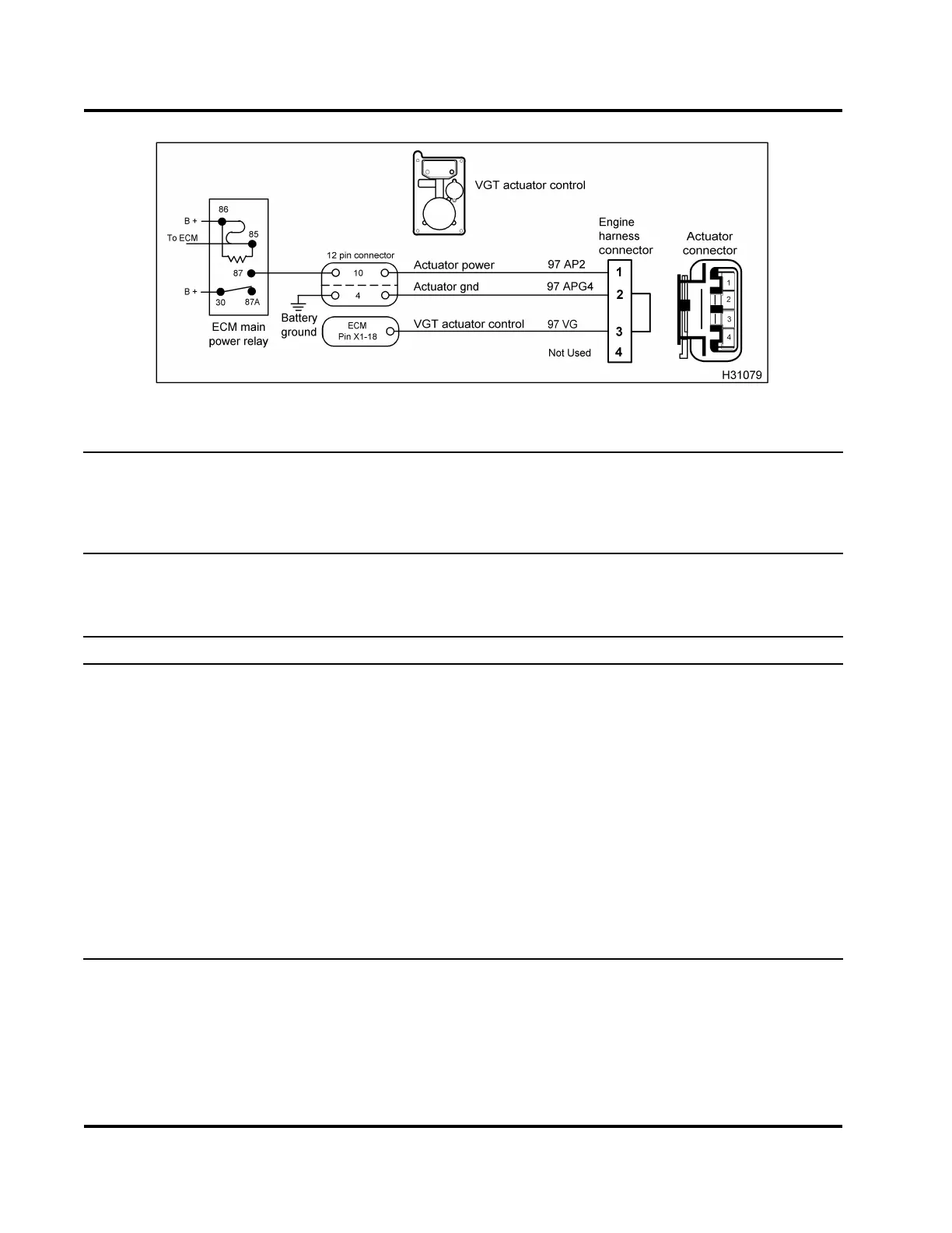
Figure 503 VGT circuit diagram
NOTE: I f an Actuator Co ntrol Voltage Check wa
s not to specification, continue w ith this check.
Turn the ignition switch to OFF when disconne
cting engine wiring harness connectors from components.
See truck Ch assis Electrical Circuit D iag ra
m M anual for circuit numbers, connector and fuse locations.
Actuator Control Voltage Check at E CM (Connect breakout box X-1 only to ECM and engine harness.
Engine harness is not connected to actuator harness. Connect 500 Ohm R esistor Harness between X1-18
and X1-6. Turn the ignition switch to ON. See “Diagnostic Software Operation” in Section 3 (page 68) for
procedure to do the Low and High Output State Tests.)
Test State/Point Setting/Spec Comment
KOEO DMM set to V - DC
X1–18 to X1– 6
DMM set to V - DC
1
DMM set to duty
cycle
2
If in specification, run the Low and High Output State
Tes ts .
If not in specification, disconnect engine harness from
breakout box harnes s and retes t.
• If not in specification, run the Low and High Output
State Tests.
•Ifinspecification, diagnose engine wiring harness.
Do Harness Resistance Check – VGT Actuator to
ECM (page 538).
Output State Test - Low DMM set to V - DC Listen and observe to verify if crank lever of VGT
actuator moves. Toggling between the Low and High
Output State Tests can be done during this test.
EGES-270-1
Read all safety instructions in the "Safety Information" section of this manual before doing any procedures.
Follow all warnings, cautions, and notes.
© August 2008 Navistar, Inc.
 Loading...


