50 1 ENGINE SYSTEMS
The sensor receives the V
REF
and returns an analog
signal voltage to the ECM. The ECM compares the
voltage with pre-programmed values to determine
pressure.
Brake Control Pressure (BCP)
The ECM monitors the BCP signal to determine the oil
pressure in the brake gallery of the high-pressure oil
rail. The BCP sensor is under the valve cover, forward
of the No . 2 fuel injector in the high-pressure oil rail.
Injection Control Pressure (ICP)
The ECM monitors the ICP signal to determine the
injection control pressure for engine operation. The
ICPsignalisusedtocontroltheIPRvalve. TheICP
sensor provides feedback to the ECM for Closed Loop
ICP control. The ICP sensor is under the valve cover,
forward of the No. 6 fuel injector in the high-pressure
oil rail.
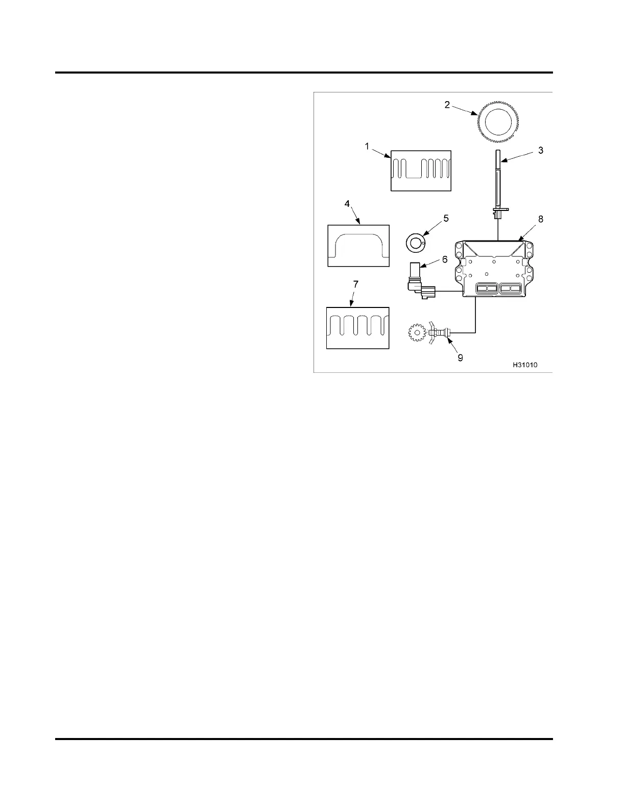
Figure 42 Magnetic pickups
1. Cranksh aft Position (CKP) signal
2. Cranksh aft position sensor timing disk
3. Crankshaft Position ( CKP) sensor
4. Camshaft position (CMP) signal
5. Camshaft with peg
6. Camshaft positio n (CMP) sensor
7. Vehicle speed signal
8. Electronic Control Mo dule (ECM)
9. Vehicle Spe ed Sensor (VSS)
Magnetic Pickup Sensors
•CKP
•CMP
• VSS
A magnetic pickup sensor generates an alternating
frequency that indicates speed. Magnetic pickups
have a two wire connection for signal and ground.
This sensor has a permanent magnetic core
surrounded by a wire coil. The signal frequency
is generated by the rotation of gear teeth that disturb
the m agnetic field.
EGES-270-1
Read all safety instructions in the "Safety Information" section of this manual before doing any procedures.
Follow all warnings, cautions, and notes.
© August 2008 Navistar, Inc.
 Loading...


