550 7 ELECTRONIC CONTROL SYSTEMS DIAGNOSTICS
WIFSensor(WaterinFuel)
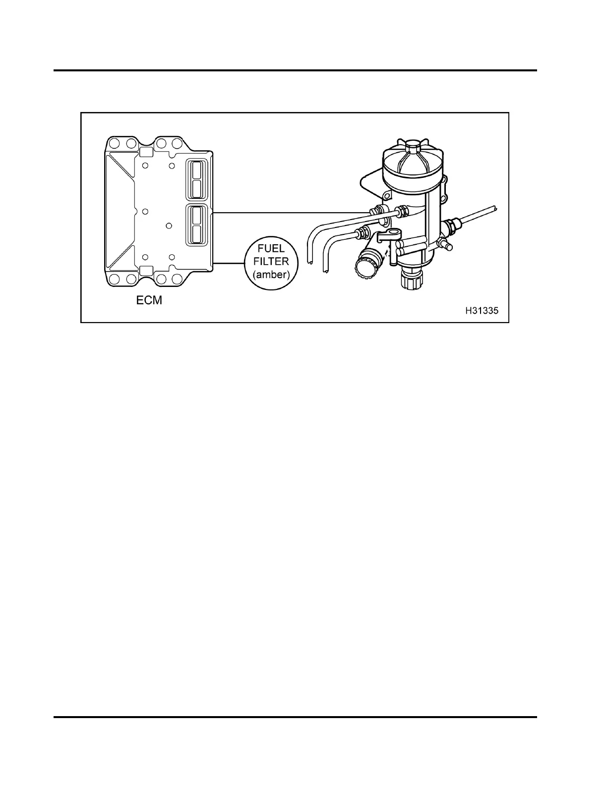
Figure 511 Function diagram for the WIF system
The function diagram for the WIF system includes the
following:
• Electronic Control Module (ECM)
•Fuelfilter assembly
• FUELFILTERlamp(amber)
The Electronic Control Module (ECM) monitors the
fuel filter header and alerts the operator when water
is present in th e fuel supply. When water is detected,
the ECM will set a Diagnostic Trouble Code (DTC) and
the amber FUEL F ILTER la mp will illum inate.
TheWIFsystemincludestheECMandthefuelfilter
assembly w ith a WIF sens or. The WIF se nsor is used
in the fuel filter assembly.
EGES-270-1
Read all safety instructions in the "Safety Information" section of this manual before doing any procedures.
Follow all warnings, cautions, and notes.
© August 2008 Navistar, Inc.
 Loading...


