552 7 ELECTRONIC CONTROL SYSTEMS DIAGNOSTICS
WIF Pin-Point Diagnostics
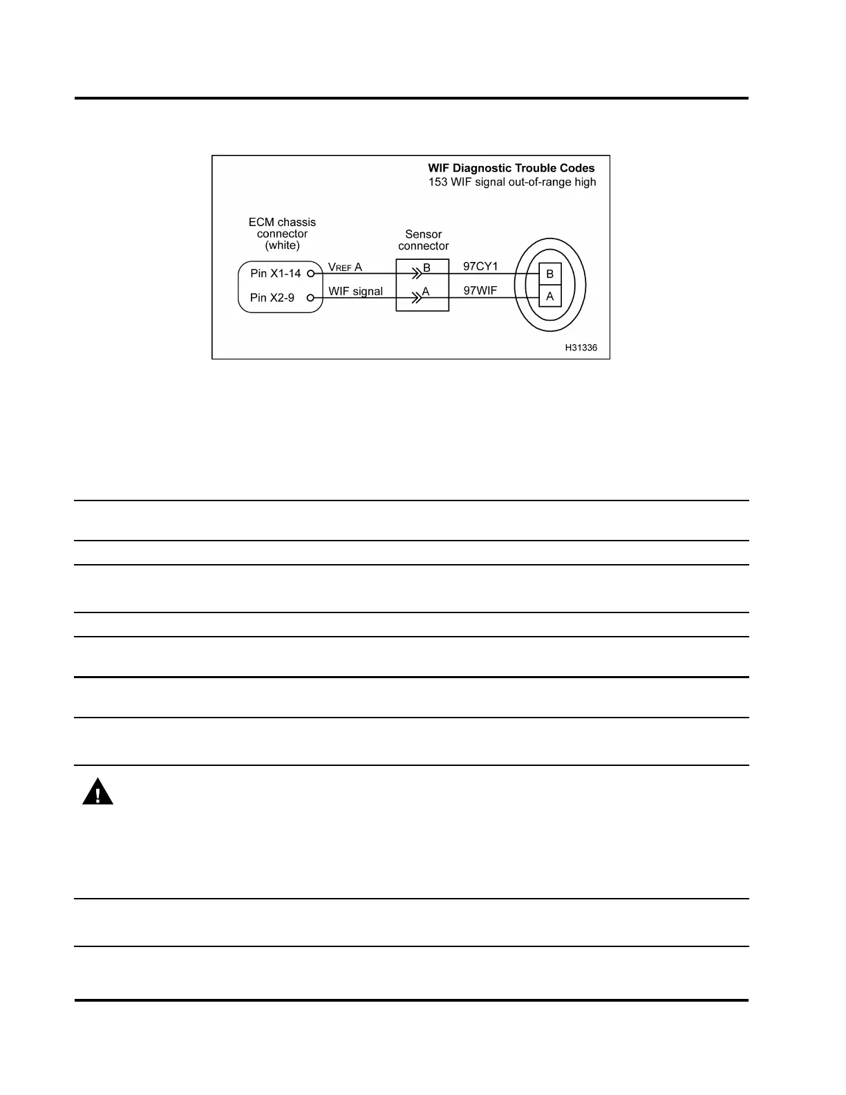
Figure 513 WIF system circuit diagram
The WIF circuit may require the use of vehi
cle
circuit diagrams. See truck Chassis Elec
trical Circuit
Diagram Manual for circuit numbers, con
nector and
fuse locations.
Voltage Checks at WIF Sensor Con nec
tor (Disconnect harness from sensor and turn the ignition switch to
ON.) Note: After removing connecto
r, inspect for damaged pins, corrosion, or loose pins. Repair as required.
Test Point
Spec Comment
Atognd 5V±0.5V
Ifvoltage<5V,checkforopenV
REF
circuit or failed ECM.
Btognd 0V
If voltage > 0 V, check for signal
circuit shorted to another circuit
Sensor Resistance Check (Disconnect connector from sensor and measure across sensor.)
AtoB
>1kΩ If < 1 kΩ, check for w ater in fuel, failed sensor, or shorted sensor
harness.
Connector Resistance Che
cks to ECM Chassis Ground (Turn the ignition switch to OFF. Disconnect
chassis connector 9260
1
.
Disconnect harness from sensor.)
AtoPinB(9260) >1kΩ If < 1 kΩ, check for short to signal ground.
BtoPinB(9260) >1kΩ If < 1 kΩ, check for short to signal ground.
WARNING: To avoid serious personal injury, possible death, or damage to the engine or vehicle,
always disconnect main negative battery cable first. Always connect the main negative battery cable
last.
Connector Resista
nce C hecks to Chassis Ground (Turn the ignition switch to OFF. Disconnect chassis
connector 9260
1
.
Disconnect negative battery cable. Disconnect harness from sensor. Use disconnected
negative battery
cable for ground test point.)
Atogndcable
>1kΩ If < 1 kΩ, check for short to chassis ground.
Btogndcable
>1kΩ If < 1 kΩ, check for short to chassis ground.
EGES-270-1
Read all safety instructions in the "Safety Information" section of this manual before doing any procedures.
Follow all warnings, cautions, and notes.
© August 2008 Navistar, Inc.
 Loading...


