CIBANO 500 PTM User Manual
130 OMICRON
3. Make sure that all cable connectors are clean and dry before being tightly connected.
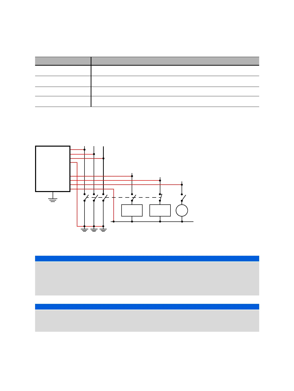
4. Connect CIBANO 500 to the trip and close coils of the circuit breaker for all phases according to the
wiring diagram displayed in Primary Test Manager and the following figure.
Figure 17-7: Connecting CIBANO 500 to the circuit breaker for the Timing test
B2
Trip B, Close, Trigger IN
1
, I clamp 2 or Disabled
B3
Trip C, Supply, Trigger IN
1
, I clamp 3 or Disabled
BN Neutral connection of outputs in group B
B4
Trigger IN
1
, I clamp 4, Motor or Disabled
1. Trigger signal starting the measurement
NOTICE
Equipment damage or loss of data possible
► Never connect CIBANO 500 between the respective AUX contacts of the trip and close coils and the
coils themselves since these contacts assure that the voltage is not applied too long to the coils.
► Connect CIBANO 500 to the circuit breaker as shown in Figure 17-7: "Connecting CIBANO 500 to
the circuit breaker for the Timing test".
NOTICE
Equipment damage or loss of data possible
► Do not connect the DC coils with false polarity to prevent damaging the free running diodes.
► Always observe the right polarity of the DC coils.
Table 17-6: Hardware configuration options of CIBANO 500 (continued)
CIBANO 500 Option
Trip coil Close coil
–
CIBANO 500
A1
A2
A3
B1
B2
BN
B4
M
AN

 Loading...


