OMICRON 149
Off-service diagnostic methods
3. Make sure that all cable connectors are clean and dry before being tightly connected.
4. Connect CIBANO 500 to the trip and close coils of the circuit breaker according to the wiring diagram
displayed in Primary Test Manager.
Measurement
To perform a measurement:
1. In the Settings and conditions area, enter the settings of the Minimum Pickup test.
AN Common neutral connection for outputs in group A
B-OUTPUT / INPUT (CAT III / 300 V)
B1 Trip or Disabled
B2 Close or Disabled
B3 Supply or Disabled
BN Common neutral connection for outputs in group B
B4 Motor or Disabled
1. Cannot be used to supply the trip or close coil because a variable voltage is needed, however it can be used to supply the
motor.
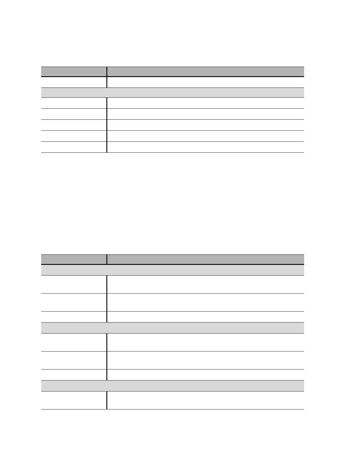
Table 17-23: Settings of the Minimum Pickup test
Setting Description
Coil supply
Supply settings
1,2
Select a preconfigured coil supply setting from the asset data or select
Custom to enter custom settings.
Coil supply voltage Rated voltage of the coil supply
Click AC or DC for AC or DC coil supply voltage respectively.
Test frequency Coil supply frequency (AC only)
Test sequence
Coil supply voltage start Start voltage of the automated test sequence to determine the minimum
pickup voltage
Coil supply voltage end End voltage of the automated test sequence to determine the minimum
pickup voltage
Coil supply voltage step Stepwise voltage increase of the automated test sequence
Motor supply
Supply source Click CIBANO 500 to supply the motor with CIBANO 500.
Click External source to supply the motor externally.
Table 17-22: Hardware configuration options of CIBANO 500 (continued)
CIBANO 500 Option

 Loading...


