OMICRON 197
Off-service diagnostic methods
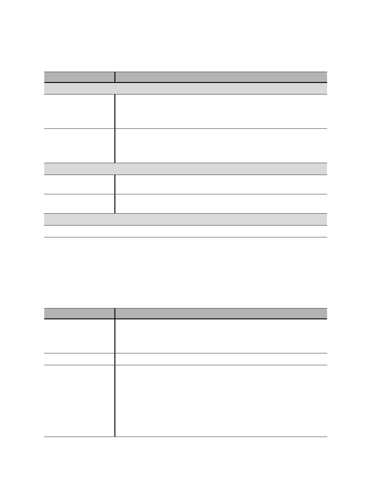
The following table explains the sequences of the Dynamic Contact Resistance test.
Contact bounce filter
Main contact Threshold value of the time interval between two consecutive bounces of
the main contact. For time intervals equal or below the threshold, the
contact is considered as closed.
Setting the value to 0.0 ms deactivates the contact bounce filter.
Auxiliary contact Threshold value of the time interval between two consecutive bounces of
the auxiliary contact. For time intervals equal or below the threshold, the
contact is considered as closed.
Setting the value to 0.0 ms deactivates the contact bounce filter.
Average coil current/voltage
Begin Start of the average coil current/voltage evaluation in percent of the time
period during which the current flows through the coil
End End of the average coil current/voltage evaluation in percent of the time
period during which the current flows through the coil
Sequence
See Table 17-51: "Dynamic Contact Resistance test sequences" later in this section.
1. Only available for PIR contact system
2. Only available for Standard contact system
3. Only available for Graphite nozzle contact system
4. The Close breaker before test check box is only active if the test sequence begins with the open command and no output is
set to Trigger IN.
5. We recommend 10 kHz to constrain the amount of created data. Higher sample rates are needed for special tests only.
Table 17-51: Dynamic Contact Resistance test sequences
Sequence Action
O With this sequence, the opening time of the circuit breaker is measured.
Only for O and C sequences we recommend performing the test twice, once
with nominal voltage and once with 20% undervoltage to assure the
functionality of the circuit breaker for a weak station battery.
C This is the sequence to measure the closing time of the circuit breaker.
OC With this sequence, a closing operation after the circuit breaker has tripped
to clear a fault is simulated.
Initially, the circuit breaker must be in the closed position. An open
command initiates the sequence, followed by a dead time to clear the fault;
and finally a close command must close the circuit breaker. This sequence
is also known as reclosing sequence. To find out the shortest reclosing time
the circuit breaker can provide, the close command is already applied while
the circuit breaker is still opening. The circuit breaker then will close after
opening as fast as possible.
Table 17-50: Advanced settings of the Dynamic Contact Resistance test (continued)
Setting Description

 Loading...


