CIBANO 500 PTM User Manual
288 OMICRON
3. Fit the shaft of the transducer into the hole of the flexible coupling and tighten the screws.
4. Fix the articulating arm by using the set screw and the joint of the screw clamp by switching the lever
to the corresponding position.
5. Connect the cable of the transducer to one digital interface of the CB TN3 module.
6. Configure the CB TN3 digital interface in Primary Test Manager.
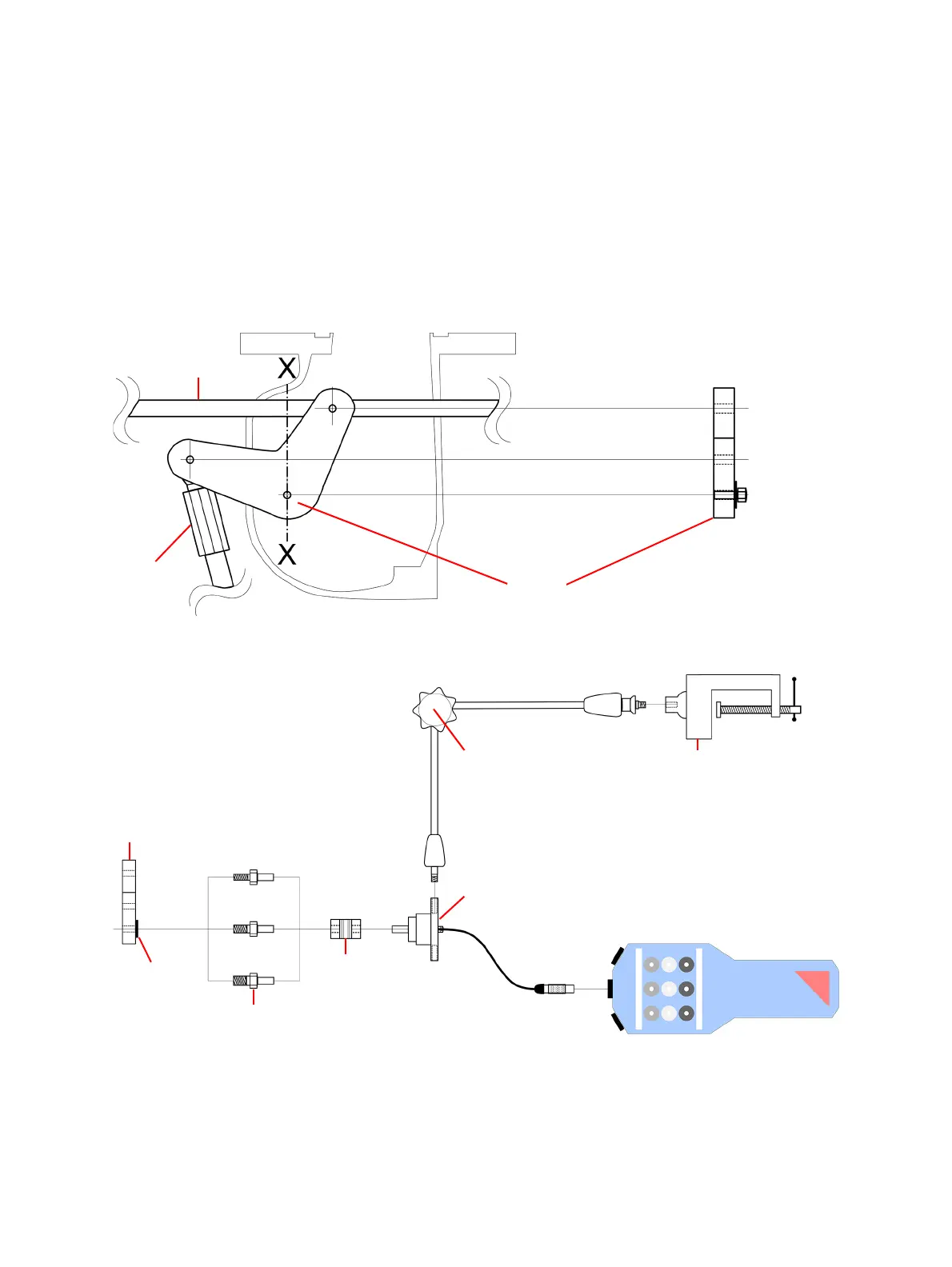
If it is possible to exchange the screw on the lever pivot, mount the travel sensor as described in
Figure 19-9 and Figure 19-10.
Figure 19-9: Lever (X-X view) where the screw at the pivot point of the lever can be exchanged
Figure 19-10: Use screw-in rods to apply OMICRON motion transducer to the drive lever of the circuit
breaker
Connecting rod
Drive rod
Drive lever
X-X view
Circuit breaker
drive lever
X-X view
Washer
Screw-in rods
Flexible coupling
M8
M10
M12
Rotary transducer
Articulating arm Parallel vice
CB TN3

 Loading...


