CIBANO 500 PTM User Manual
318 OMICRON
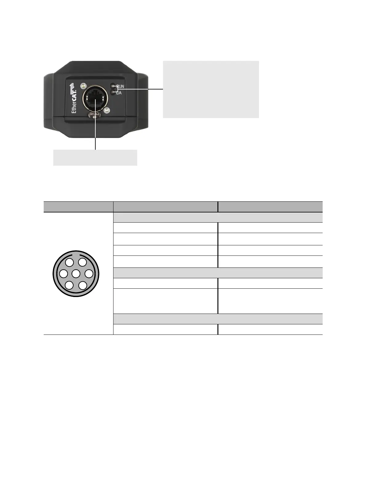
Figure 22-4: Bottom view of the CB TN3 module
Table 22-6: Pin assignment of the digital interface connector
Layout Pin Description
Differential signals
1A
2
!A
1
1. Inverted signal
3B
4
!B
1
Supply voltage
5 (reserved for future use) +5 V
6 +5 V…+30 V
(set by the user in Primary Test
Manager)
Grounding
7GND
Two green LEDs indicating the EtherCAT
®
state.
RUN: Signals the state of the EtherCAT
®
state machine.
L/A: Signals the state of the physical link
and activity on this link.
LEDs with the same functionality are also
on the side panel of CIBANO 500 (see
3.2.2 "Side panel" on page 18.)
EtherCAT
®
connector for connecting
the CB TN3 to CIBANO 500

 Loading...


