134
Remote I/O Terminals with Transistors Section 5-5
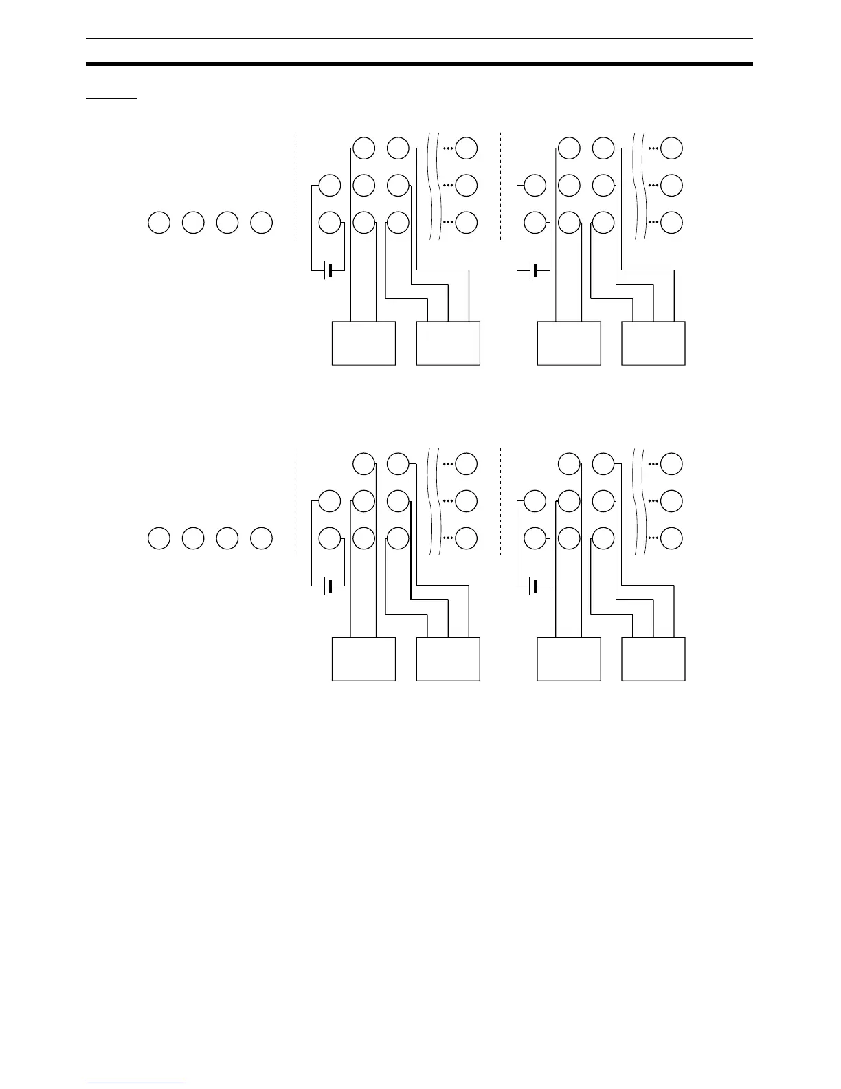
Wiring
DRT2-ID16TA (NPN)
DRT2-ID16TA-1 (PNP)
Note 1. V1 is not connected internally to V2, and G1 is not connected internally to
G2. Connect them carefully.
Do not connect anything to the reserved terminals.
2. Wire colors have been changed according to revisions in the JIS standards
for photoelectric and proximity sensors. The colors in parentheses are the
wire colors prior to the revisions.
7
V1
G1
1
V1
G1
0
V1
G1
V1
G1
−+
15
V2
G2
9
V2
G2
8
V2
G2
V2
G2
−+
Brown (white)
Blue (black)
Blue (black)
Brown (red)
Black (white)
Brown (white)
Blue (black)
Blue (black)
Brown (red)
Black (white)
2-wire sensor
(e.g., limit switch)
2-wire sensor
(e.g., limit switch)
3-wire sensor with
NPN output
(photoelectric or
proximity sensor)
3-wire sensor with
NPN output
(photoelectric or
proximity sensor)

 Loading...


