164
Connector Terminals with Transistors Section 5-6
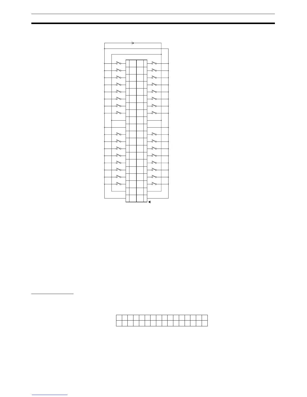
DRT2-ID32ML-1 (PNP)
Note 1. V terminals are connected internally, as are the G terminals. Connect them
carefully.
2. Wire the V terminals and G terminals correctly so that the following func-
tions operate properly.
• I/O Power Status Monitor
• Contact Operation Counter
• Total ON Time Monitor
• Function preventing malfunction caused by inrush current at startup.
If these functions are not being used, input signals will be received even if
the G terminals of the DRT2-ID32ML or V terminals of the DRT2-ID32ML-
1 are not connected.
I/O Allocations The first word allocated to the Remote Input Terminal is referred to as “word
m.” Given this, the bit and word allocations to MIL connector pin numbers are
as shown in the following diagram.
24 V DC
40
VV
39
38
GG
37
36 35
34
Wd
m+1
09
Wd
m+1
01
Wd
m+1
08
Wd
m+1
00
33
32
Wd
m+1
02
Wd
m+1
10
31
30
Wd
m+1
03
Wd
m+1
11
29
28
Wd
m+1
04
Wd
m+1
12
27
26
Wd
m+1
05
Wd
m+1
13
25
24
Wd
m+1
06
Wd
m+1
14
23
22
Wd
m+1
07
Wd
m+1
15
21
20
VV
19
18
GG
17
16 15
14
Wd m
01
Wd m
09
Wd m
00
Wd m
08
13
12
Wd m
02
Wd m
10
11
10
Wd m
03
Wd m
11
9
8
Wd m
04
Wd m
12
7
6
Wd m
05
Wd m
13
5
4
Wd m
06
Wd m
14
3
2
Wd m
07
Wd m
15
1
15 14 13 12 11 10 9 8 7 6 5 4 3 2 1 0
25 27 29 31 33 35 37 39 26 28 30 32 34 36 38 40
5
Wd m
Wd m+1 7 9 11 13 15 17 19 6 8 10 12 14 16 18 20
Bit
16 inputs
16 inputs

 Loading...


