171
Connector Terminals with Transistors Section 5-6
Output Specifications
Note Do not allow the total load current to exceed 2 A and do not allow the load cur-
rent on either the V or G terminal to exceed 1 A.
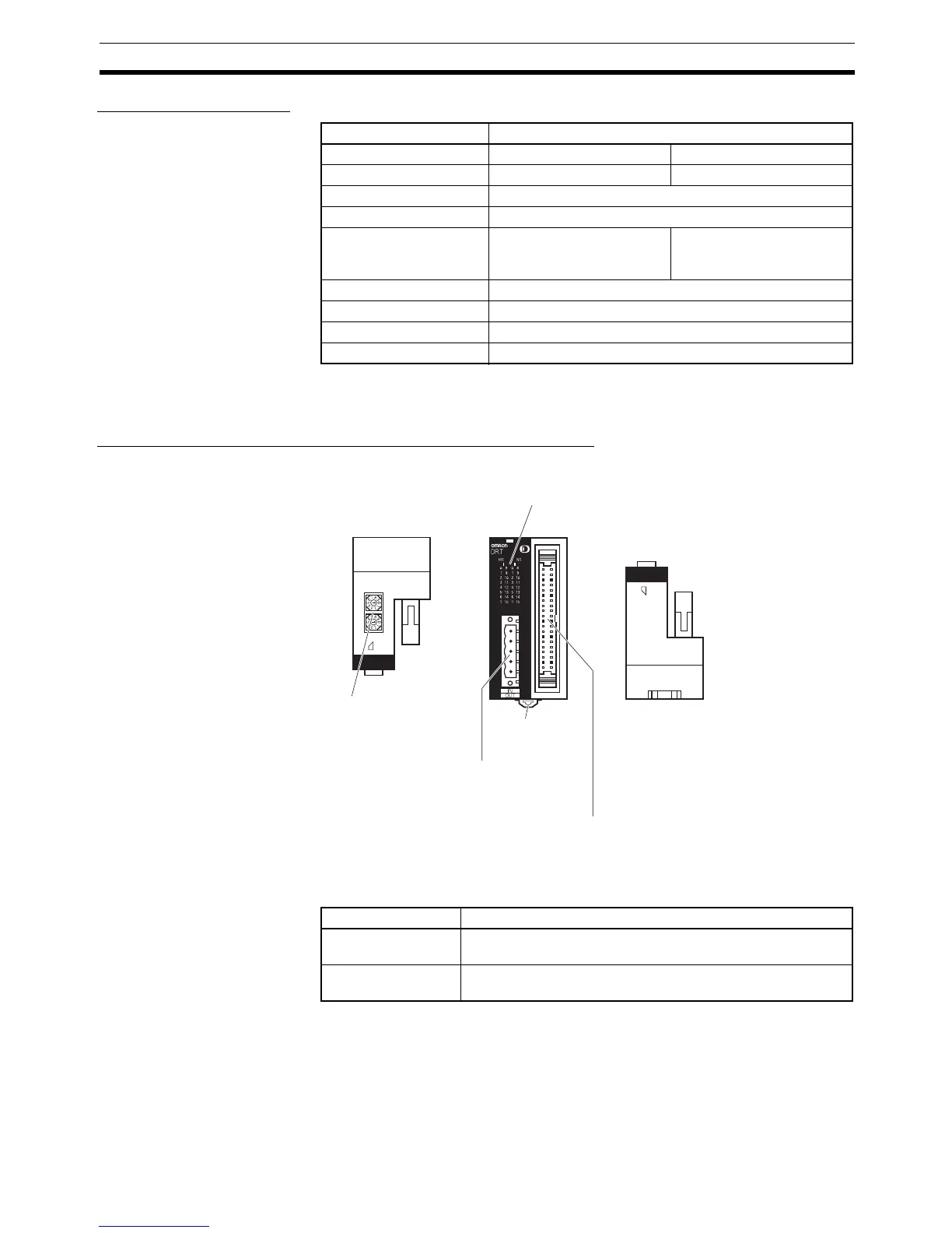
Components of the DRT2-MD32ML and DRT2-MD32ML-1
I/O Indicators
Note m: The first word allocated for the Remote I/O Terminal’s IN Area.
n: The first word allocated for the Remote I/O Terminal’s OUT Area.
Item Specification
Model DRT2-MD32ML DRT2-MD32ML-1
Internal I/O common NPN PNP
Output points 16 points
Rated output current 0.3 A/point, 2 A/common (see note)
Residual voltage 1.2 V max. (at 0.3 A,
between each output termi-
nal and G)
1.2 V max. (at 0.3 A,
between each output termi-
nal and V)
Leakage current 0.1 mA max.
ON delay time 0.5 ms max.
OFF delay time 1.5 ms max.
Number of circuits 16 points with one common
×10)
(×1)
2
Top panel Front panel Bottom panel
DeviceNet indicators
Indicate the status of the Slave, communications,
and I/O (lit when I/O is ON, I = inputs, II = outputs).
Rotary switches
Set the node address.
DIN track
mounting hooks
Communications
connector
I/O connector (MIL)
Connects the 16 inputs and 16 outputs via a MIL connector.
The MIL cable is sold separately.
Name Meaning
I0 to I15 Indicate the status of bits (contacts) 0 to 15 in word m. Lit
when input is ON; not lit when input is OFF.
II0 to II15 Indicate the status of bits (contacts) 0 to 15 in word n. Lit when
output is ON; not lit when output is OFF.

 Loading...


