293
Overview of Analog Slaves Section 7-1
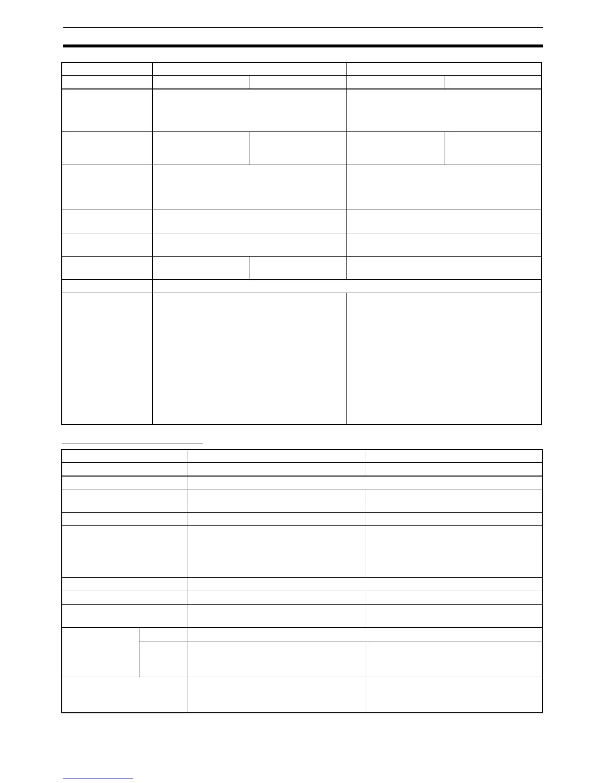
Analog Output Terminals
Data allocated in
Master
Only analog input values for 4 inputs Default: Analog input values for 4 points
The Configurator can be used to allocate peak,
bottom, top, and valley values, rate of change,
comparator results, Generic Status Flags, etc.
Input switching (Sets
number of AD con-
version points)
Supported. (Set using
DIP switch: Select
either 2 or 4 points)
Not supported. Supported (Set using
Configurator: Select
from 1 to 4 points)
Not supported.
Input range switching Set using rotary switches: Inputs 0 and 2 share
one setting, and Inputs 1 and 3 share another
setting.
• Using DIP switch: Inputs 0 and 1 share set-
ting, Inputs 2 and 3 share setting.
• Using Configurator: Inputs 0 to 3 set sepa-
rately.
Node address setting Set using DIP switch. Set using the rotary switches or the Configura-
tor.
Baud rate setting Set using DIP switch. Automatically detected: Uses baud rate set for
Master Unit.
Moving average Supported. (Set using
DIP switch.)
Not supported. Supported. (Set using Configurator.)
Off-wire detection Supported.
Scaling, offset com-
pensation, peak/bot-
tom hold, top/valley
hold, rate of change
operations, compara-
tor, user adjustment
(maintenance func-
tion), cumulative
counter (mainte-
nance function), last
maintenance date
(maintenance func-
tion)
Not supported. Supported. (Set using Configurator.)
Slave DRT1 Series DRT2 Series
Model DRT1-DA02 DRT2-DA02
Analog points 2 outputs
Output signal range 1 to 5 V, 0 to 10 V, –10 to 10 V, 0 to 20 mA,
4 to 20 mA (0 to 5 V not supported)
0 to 5 V, 1 to 5 V, 0 to 10 V, –10 to 10 V, 0 to
20 mA, 4 to 20 mA
Conversion time 4 ms/2 points 2 ms/2 points
AD conversion data 0 to 5 V, 1 to 5 V, 0 to 10 V, 0 to 20 mA, 4 to
20 mA: 0000 to 1770 hex
–10 to 10 V: 8BB8 to 0BB8 hex
Note Signed binary
0 to 5 V, 1 to 5 V, 0 to 10 V, 0 to 20 mA, 4 to
20 mA: 0000 to 1770 hex
–10 to 10 V: F448 to 0BB8 hex
Note Two’s complement
Resolution 1/6,000 (full scale)
Unit power supply Supplied by local power supply terminal. Supplied by communications power supply.
Communications power sup-
ply current consumption
30 mA max. 120 mA max.
Overall accuracy 25°C
Voltage output:
±0.3% FS; Current output: ±0.4% FS
−10 to
55°C
0 to 55°C:
Voltage output: ±0.6% FS; Current output:
±0.8% FS
−10 to 55°C:
Voltage output:
±0.6% FS; Current output:
±0.8% FS
Data allocated in Master Only Analog output values for 2 outputs Default: Analog output values for 2 points
The Configurator can be used to allocate
Generic Status Flags.
Slave DRT1 Series DRT2 Series
Model DRT1-AD04 DRT1-AD04H DRT2-AD04 DRT2-AD04H

 Loading...


