326
Analog Input Terminals Section 7-4
Allocating I/O Data in
the Master
Use one of the following methods to select data for allocating in the Master
and then perform remote I/O communications.
1,2,3... 1. Allocating only analog input values (default I/O data) in the Master.
2. Allocating selected I/O data (patterns) in the Master (fixed I/O data combi-
nations).
3. Allocating user-defined I/O data in the Master (user-defined I/O data com-
binations).
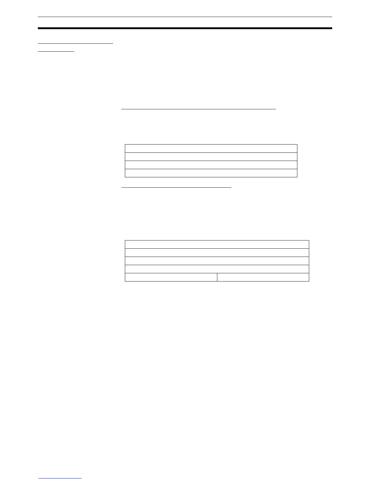
■ Allocating Analog Input Values (Default I/O Data) Only
When using the Analog Input Terminal’s default settings, only the analog input
values are selected as I/O data and allocated in the four words (eight bytes) of
the Master’s IN Area, as shown in the following diagram.
■ Allocating Selected I/O Data (Patterns)
The analog data selected from the data on which math operations have been
performed is combined with other data such as Status Flags and allocated in
the Master.
Example: Allocating Analog Data 1 + Top/Valley Detection Timing Flags in the
Master.
The following method can be used to allocate data from the Configurator.
Setting Using the DeviceNet Configurator
1,2,3... 1. Double-click the icon of the Analog Slave to be set in the Main Window and
open the Edit Device Parameters Window. (From the Maintenance Mode
Window, click the right mouse button over the Slave icon and select Pa-
rameters and Edit.)
15 0
Analog input value for Input 0
Analog input value for Input 1
Analog input value for Input 2
Analog input value for Input 3
15 8 7 0
Analog Data 1 for Input 0
Analog Data 1 for Input 1
Analog Data 1 for Input 2
Analog Data 1 for Input 3
Top Detection Timing Flag Valley Detection Timing Flag

 Loading...


