37
DeviceNet Remote I/O Communications Section 3-2
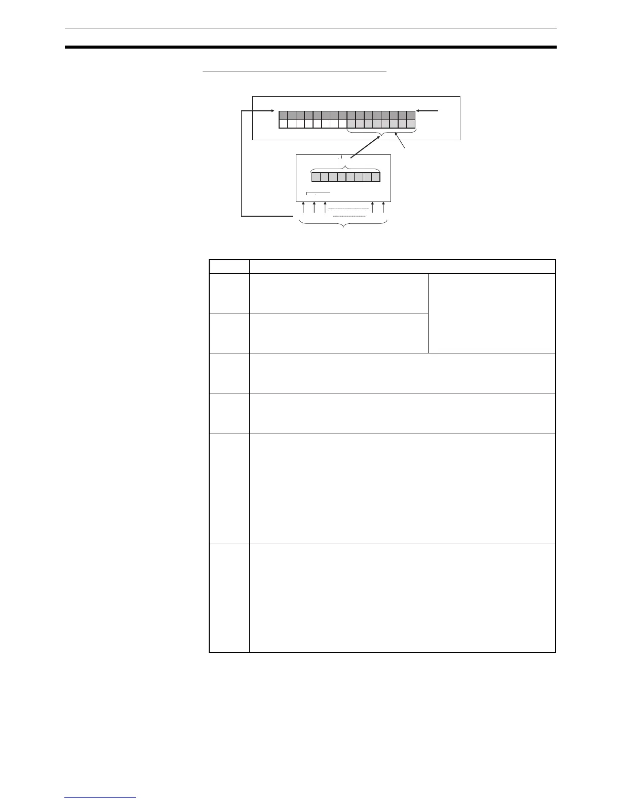
■ Example of Allocation Using Method 2
The Generic Status Flags are as follows:
Bit Contents
0 Basic Unit's I/O Power Status Flag
0: I/O power supply ON
1: I/O power supply OFF
See note 1.
1 Expansion Unit's I/O Power Status Flag
0: I/O power supply ON
1: I/O power supply OFF
2 Network Power Voltage Drops Flag
0: Normal (Higher than set monitor value)
1: Error (Same as or lower than set monitor value)
3 Unit Maintenance Flag
0: Within range (Lower than set monitor value)
1: Out of range (Same as or higher than set monitor value)
4 Sensor Disconnected Flag (Screw-less Clamp Input and I/O Terminals, and
Environment-resistive Input Terminals only) or External Load Disconnected
Flag (Screw-less Clamp Output and I/O Terminals only)
0: Connected (all inputs connected)
1: Disconnected (at least one input is not connected)
Cumulative Counter Flag (Analog Input Terminals and Temperature Input
Terminals)
0: Normal
1: Error (monitoring set value exceeded)
5 Short-circuited Flag (Sensor Connector Terminals, Screw-less Clamp Input
and I/O Terminals, and Environment-resistive Input Terminals only), or
External Load Short-circuited Flag (Environment-resistive Output Termi-
nals, Sensor Connector Terminals, I/O Units only)
0: Normal I/O (all I/O points normal)
1: Short-circuited I/O (one or more I/O point short-circuited)
Unit Error Flag (Analog Input Terminals and Temperature Input Terminals)
0: Normal
1: Error (Data conversion stopped during to error in Unit.)
15
15 8 7 0
14 13
0 1
Master CPU Unit
IN Area
Status: 8 points
Node address 1
DRT2-series Slave
Status
Real inputs (e.g., 16 points)
Real inputs: 16 points

 Loading...


