43
DeviceNet Remote I/O Communications Section 3-2
Default Connection Path (General-purpose Slave)
Allocating User-
defined Data
This method is possible only with a CS/CJ-series DeviceNet Unit and user-
defined allocations.
In the Master’s Edit Device Parameters Window, select the Smart Slave to be
set, and specify the connection in the Advanced Setting Window. Select the
I/O data (pattern) in the connection path setting.
In the Master’s Edit Device Parameters Window, allocate Slave I/O.
Note 1. For details on connections and connection paths, refer to Appendix B De-
viceNet Connections in the DeviceNet Units Operation Manual (W380).
2. Master Unit settings take precedence and so it is not necessary to set the
Slave’s default connection path.
The setting example below is for allocating 16 inputs, 8 outputs, and Generic
Status Flags for a General-purpose Slave. For details on the setting method
for Analog Slaves, refer to 7-4-2 I/O Data Allocation Methods.
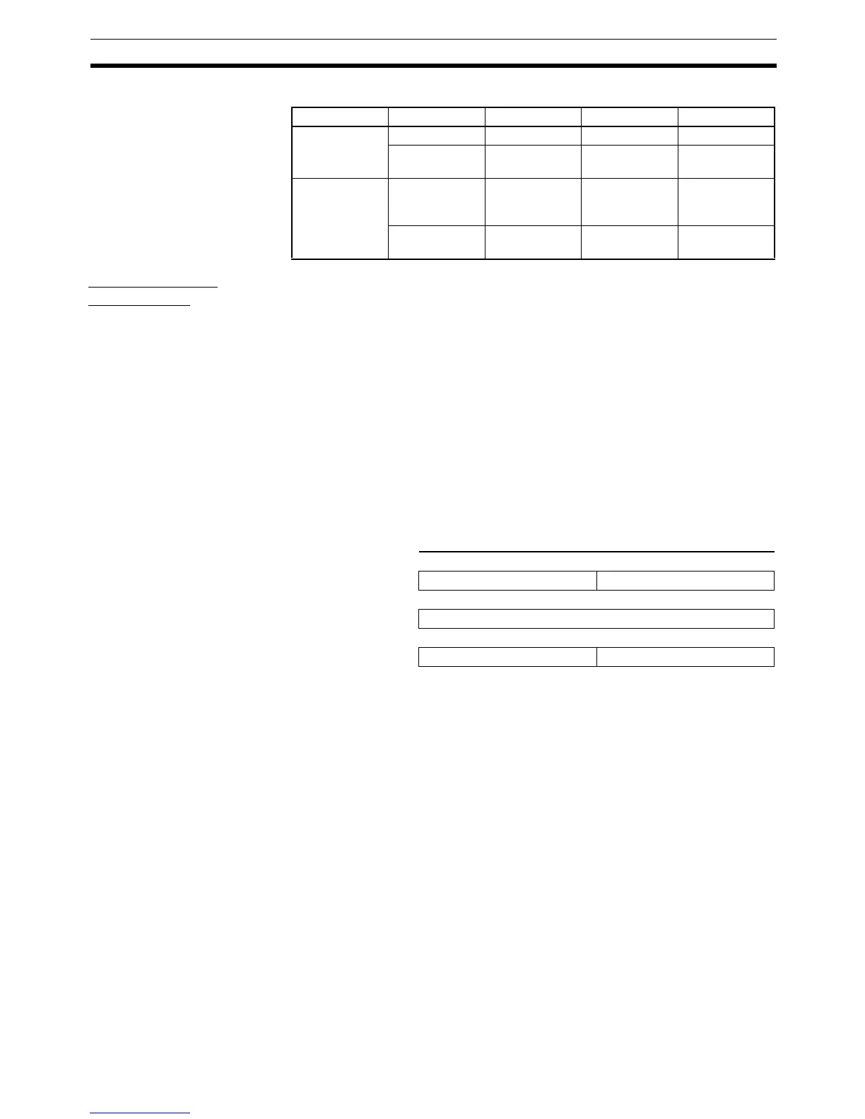
Example: Using 16 inputs, 8 outputs, and status information.
Selection IN/OUT Input Unit Output Unit I/O Unit
Setting 1 (I/O
Data)
(default setting)
IN data Real input data None Real input data
OUT data None Real output
data
Real output
data
Setting 2 (I/O
Data+Status)
IN data Real I/O data +
status informa-
tion
Status informa-
tion
Real input data
+ status infor-
mation
OUT data None Real output
data
Real output
data
Address 15 0
CIO 3200 8 outputs
:
CIO 3300 16 inputs
:
CIO 3500 Generic Status Flags

 Loading...


