139 HD-1500 Platform User's Manual 31500-000 Rev A
5.2 Considerations
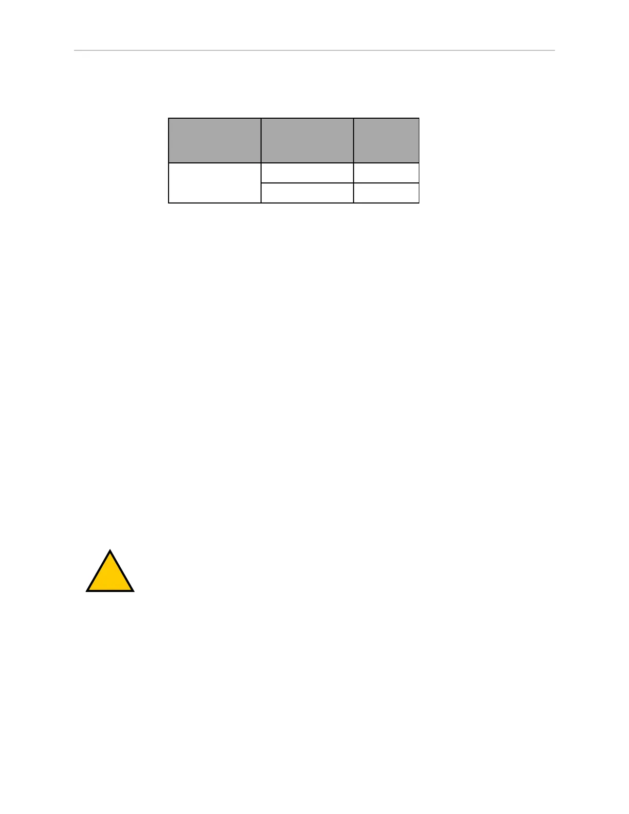
Momentary current spikes over these thresholds will activate current limiting protection caus-
ing power loss at the connector. Simultaneous inrush loads might trip the over current pro-
tection at the battery. The maximum permitted duration of an overcurrent level is as follows:
Current
Protection Level
(A)
Overcurrent
Level (A)
Overload
Duration
(ms)
50
(user power)
100 100
205 1
Payload Attachment Location
The HD-1500 chassis is where you attach and secure your payload structure to the platform.
The user panel allows you to make the necessary electrical connections from your payload
structure to the AMR Controller.
Considerations when designing your payload structure are:
l
Provide access to the payload attachment location for serviceability. You must ensure
that the mechanical connection points, as well as the electrical connections are con-
veniently accessible.
l
Always take care to not damage any cabling between your payload structure and the
HD-1500. Provide adequate slack in all cables, or include connectors. Also, provide
adequate strain relief where more flexibility is required.
l
Label all cables for accurate reconnection.
Payload Dimensions and Design
To maintain safe operation of the AMR when adding a payload, the following considerations
might apply.
Avoid Projections and Overhangs
Your payload structure should not overhang or project beyond the outer dimensions of the plat-
form. Doing so might place parts of the structure outside the safety envelope provided by the
safety lasers.
WARNING: If you do design an overhanging payload, you must:
l Contact your OMRON representative to change the size of the safety
scanning lasers' safety zones.
l Repeat the safety commissioning. See: E-Stop Commissioning on page
253.
l Modify the Robot Physical: General parameters to change the AMR's
width, LengthFront, LengthRear, and potentially its Radius. See: Fleet
Operations Workspace Core User's Manual (Cat. No. I635).
When making these modifications, ensure that the AMR's accurate
dimensions are used during path planning and obstacle avoidance.
Side lasers are useful if the overhang might cause the AMR to encounter obstacles that are not
visible to the safety scanning lasers, or the low lasers.