8
Inputting
Master
Speed
Frequency
Reference
Only
(European
Model)
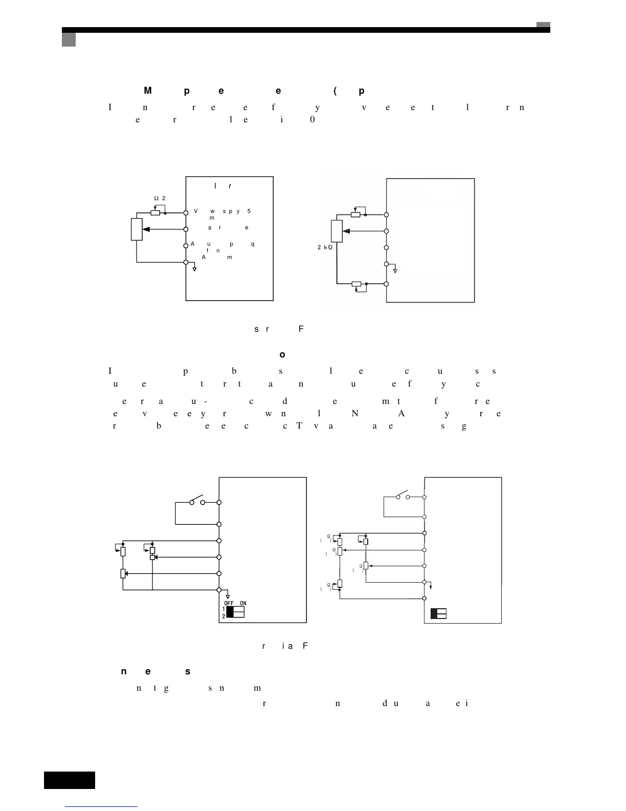
If
inputting
the
master
speed
frequency
reference
only,
input
the
voltage
reference
to
control
circuit
terminal
A1.
The
voltage
range
canbe
selected
by
setting
H3-01.
Fig 6.6 Master Speed Frequency Reference Input
2-Step
Switching:
Master/Auxiliary
(European
Model)
If
performing
2-step
switching
between
master
and
auxiliary
speed
frequencies,
input
the
master
speed
fre-
quency
reference
to
control
circuit
terminal
A1,
and
input
the
auxiliary
speed
frequency
reference
to
A2.
When
terminal
S3
(multi-step
speed
command
1)
is
OFF,
terminal
A1
(master
speed
frequency
reference)
will
be
the
Inverter
frequency
reference,
and
when
terminal
S3
is
ON,
terminal
A2
(auxiliary
speed
frequency
ref-
erence)
will
be
the
Inverter
frequency
reference.
The
voltage
range
can
be
selected
by
setting
H3-01.
Fig 6.7 Master/Auxiliary Frequency Reference Input
Setting
Precautions
When
inputting
a
voltage
signal
to
terminal
A2,
observe
the
following
precautions.
• Turn
OFF
pin
2
on
DIP
switch
S1
for
switching
between
voltage
and
current
(factory
setting
is
ON).
Inverter
A1 (Master speed frequency
reference)
+V (Power supply: 15 V,
20 mA)
A2 (Auxiliary speed frequency
reference)
AC (Analog common)
2 kΩ (2 W)
When H3-01 = 0 When H3-01 = 1
Inverter
A1 (Master speed frequency
reference)
+V (Power supply: 15 V,
20 mA)
A2 (Auxiliary speed frequency
reference)
AC (Analog common)
2 kΩ (2 W)
(2 W)
−V (Power supply: −15 V,
20 mA)
2 kΩ (2 W)
2 kΩ
(2 W)
1
2
OFF ON
2 k
2 W
2 k
2 W
2 k
2 W
2 k
2 W
0 to -10 V
0 to +10 V
Input
0 to 10 V
input
Inverter
+V (Power supply: 15 V,
20 mA)
A1 (Master speed frequency
reference)
0 to 10 V input
DIP switch S1
SC Sequence common
S3 Multi-step speed
command 1
Master/
Auxiliary
A2 (Auxiliary speed frequency
reference)
AC (Analog common)
Inverter
+V (Power supply: 15 V,
20 mA)
A1 (Master speed fre-
quency reference)
0 to 10 V input
DIP switch S1
SC Sequence common
S3 Multi-step speed
command 1
Master/
Auxiliary
A2 (Auxiliary speed fre-
quency reference)
AC (Analog common)
When H3-01 = 0 When H3-01 = 1
−V (Power supply: −15 V, 20 mA)

 Loading...


