108
Length
<l>
Set
the
length
of
the
data.
All
communications
with
the
3G3RV
are
performed
in
byte
units.
Select
1
Byte
and
BIN.
Select
No
for
read-
ing
data
because
there
is
no
data
to
be
read.
Address
<a>
Set
the
addresses
of
the
Slaves.
In
this
example,
the
Slave
addresses
are
set
in
S
+
2,
S
+
5,
and
S
+
8.
Therefore,
retrieve
the
data
from
those
locations.
The
address
is
set
in
the
LSB
of
each
word.
To
read
the
byte,
select
Variable
Reverse,
otherwise
the
data
will
be
read
from
the
MSB.
Then
click
on
Edit
Variable
with
the
left
button
of
the
mouse.
Select
Read
R
()
and
set
Data/Address
to
the
operand
(3N
+
2)
using
the
number
(N)
of
times
to
repeat
the
step.
Set
Edit
length
to
1
byte
as
a
default.
If
the
default
value
has
been
changed,
set
it
to
0N
+
1.
Data
Set
the
expected
response
in
detail.
• Response
to
the
RUN
Command
and
Frequency
Reference
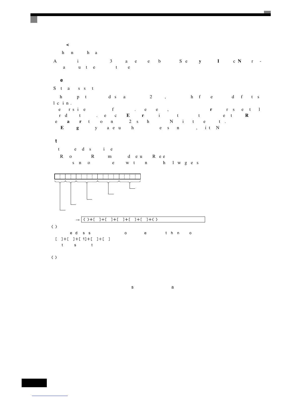
The
response
to
the
DSR
message
written
consists
of
the
following
items.
Fig 6.70 Response to DSR Message Written
a
The Slave address is set in the address box. Insert the address with the Insert icon.
10 00 01 00 02
Set the constants contained in the response.
Use Set Constant and set the constants in Hex.
c
The check code is set in the check code box. Insert the check code by using the Insert icon. All the data including the
address data before the check code is used. Mark all the items if the PST is used. The check code is automatically set
by the CX-Protocol.
1000010002
Slave address (Set with <a>)
Function code (Write 10)
Write start register number (RUN command: 0001)
Number of write data registers: 2
CRC-16 check (Set with <c>)
Set data
a 10 00 01 00 02 c

 Loading...


