09
• Response
to
the
Inverter
Status
Read
The
response
to
the
DSR
message
to
request
the
Inverter
status
in
register
002C
Hex
consists
of
the
fol-
lowing
items.
Fig 6.71 Response to DSR Message Read
nLadder
Program
Connect
the
PST
and
the
Communications
Board,
and
read
the
Communications
Board
system
settings
from
the
PST.
Set
the
start/stop
bits
both
to
1
bit,
and
data
length
to
8
bits.
Transfer
the
created
protocol
to
the
Communications
Board.
The
following
example
describes
how
to
control
the
Inverter
with
this
protocol.
nMemory
Allocations
Starting
Communications
and
Status
Signals
IMPORTANT
Before using this program in your system, be sure to check the word and data memory allocations and
change them if necessary so that there will be no word or data memory duplication.
This program will stop all communications if a communications error or fault occurs. Be sure to set H5-05 for
communications error detection selection to 1 (effective) and H5-04 for communications error detection
operation selection to 0 through 2 so that the system will stop with time-over detection.
Word Functions
common
to
all
Slaves
Inverter
control
communications
(continued
when
set
to
ON)
Communications
error
output
(on
hold
when
a
communications
error
or
fault
occurs
Communications
fault
reset
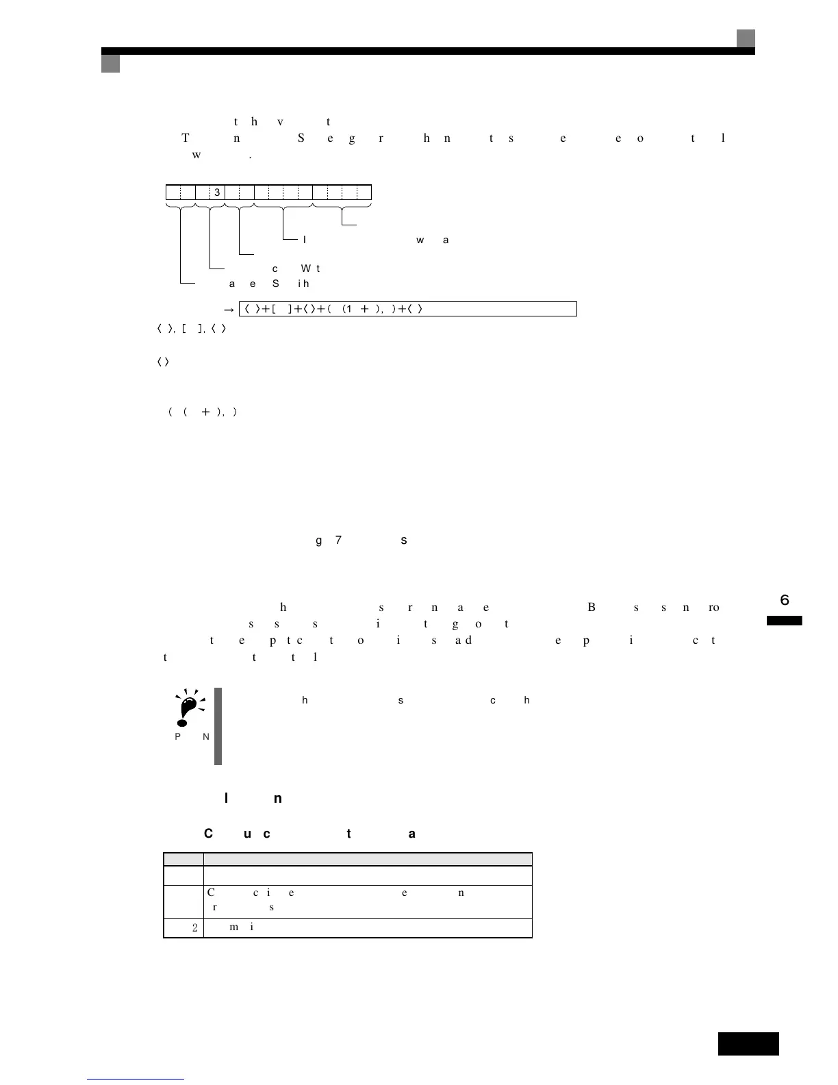
a 03 l W 1N 1 2 c
03
Slave address (Set with <a>)
Function code (Write 10)
Inverter status data (Set with variable)
CRC-16 check (Set with <c>)
Set data
Number of bytes of attached data (Set with <l>)
a 03 c
The address data, constant data, and check code data are the same as the above.
l
The length is set in the length box. Insert the length by using the Insert icon. The length is the number of bytes of the
succeeding data (W(1N + 1), 2). The length is automatically set by the CX-Protocol.
W 1N 1 2
The Inverter’s actual data is to be sent. This example selects Variable and Write W () (ntlp: English reference
mistakenly(?) says Read R () here) and sets the operand. Set the data to 1N + 1 because the RUN command data
uses two bytes each from D + 1, D + 2, and D + 3. (ntlp: English reference mistakenly(?) says the RUN command data
uses four bytes each from D + 3, D + 6, and D + 9. here)
Set Edit Length to 0N + 2 so that it will be set to two bytes.

 Loading...


