EasyManua.ls Logo

Omron SYSMAC CV Series User Manual

Omron SYSMAC CV Series
636 pages
To Next Page IconTo Next Page
To Previous Page IconTo Previous Page
Page #433 background imageLoading...
Page #433 background image
421
Control Data The control words, beginning with C, specify the number of bytes of control data
to be sent, the number of bytes of response data to be received, the destination
node, and other parameters. Some control data parameters depend on whether
a transmission is being received in a SYSMAC NET Link System or a SYSMAC
LINK System.
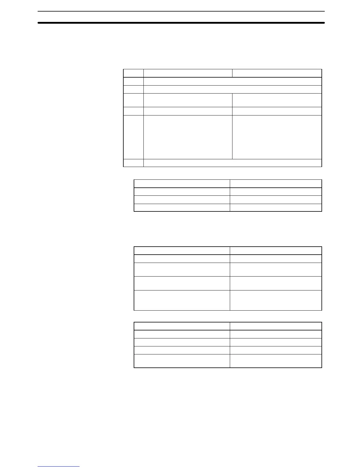
Word Bits 00 to 07 Bits 08 to 15
C Number of bytes to send (0 to 1990, i.e., $0000 to $07C6)
1
C+1 Number of bytes to receive (0 to 1990, i.e., $0000 to $07C6)
1
C+2 Destination network address
(0 to 127, i.e., $00 to $7F)
2
Bits 08 to 11: ($0 to $F)
3
Bits 12 to 15: Set to 0.
C+3 Destination unit address
4
Destination node number
5
C+4 Bits 00 to 03:
No. of retries (0 to 15 in
hexadecimal,
i.e., $0 to $F)
Bits 04 to 07:
Set to 0.
Bits 08 to 11:
Transmission port number
($0 to $7)
Bit 12 to 14:
Set to 0.
Bit 15: ON: No response.
OFF: Response returned.
C+5 Response monitoring time ( $0001 to $FFFF = 0.1 to 6553.5 seconds)
6
Note 1. Maximum number of bytes that can be sent or received:
System Max. number of bytes
SYSMAC NET Link $07C6 (1990)
SYSMAC LINK $021E (542)
SYSMAC BUS/2 $021E (542)
2. Set the destination network address to $00 when transmitting within the
same network.
3. The BASIC Unit interrupt number when a BASIC Unit is designated.
4. Indicates a Unit as shown in the following table.
Unit Setting
PC $00
SYSMAC NET Link or SYSMAC LINK
Unit
$10 to $1F: Unit numbers 0 to F
$FE: The local Unit
SYSMAC BUS/2 Master, BASIC Unit,
or Personal Computer Unit
$10 to $1F: Unit numbers 0 to F
SYSMAC BUS/2 Group 2 Slave $90 to $CF:
Unit number+90+10×Master
address
5. The destination node number can have the following values:
System/type of transmission Possible values
SYSMAC NET Link System $01 to $7E (nodes 1 to 126)
SYSMAC LINK System $01 to $3E (nodes 1 to 62)
Broadcast to all nodes in network $FF
Transmit within the PC
(to/from CPU Bus Units)
$00
6. Designates the length of time that the PC retries transmission when bit 15 of
C+3 is OFF and no response is received. The default value is $0000, which
indicates 2 seconds.
7. Transmissions cannot be sent to the PC executing CMND(194) (i.e., the
Unit cannot be specified as $00 and the destination node number set to
$00).
Precautions C through C+5 must be within the values specified below. To be able use of
CMND(194), the PC must have a SYSMAC NET Link, SYSMAC LINK Unit, or
SYSMAC BUS/2 Remote I/O Master Unit mounted.
Network Instructions Section 5-36

Table of Contents

Question and Answer IconNeed help?

Do you have a question about the Omron SYSMAC CV Series and is the answer not in the manual?

Omron SYSMAC CV Series Specifications

General IconGeneral
SeriesSYSMAC CV Series
TypePLC
Input Voltage100 to 240 VAC, 24 VDC
Number of InputsVaries by model
Number of OutputsVaries by model
I/O CapacityUp to 2048 points
I/O PointsVaries by model
Communication PortsRS-232C, RS-422/485
Programming LanguageLadder Logic
Power Supply100-240V AC or 24V DC
MountingDIN rail mounting
Operating Temperature0°C to 55°C

Summary

PRECAUTIONS

2 General Precautions

User must operate product per specifications; consult OMRON for non-manual conditions or critical systems.

3 Safety Precautions

Precautions regarding power supply, terminal touching, disassembly, repair, and battery handling.

4 Operating Environment Precautions

Guidelines for environmental conditions for PC system installation and operation.

5 Application Precautions

Precautions for safe PC system usage, grounding, power supply, wiring, and program changes.

SECTION 1 Introduction

SECTION 2 Hardware Considerations

2-3 Memory Cards

Covers file memory used to store programs and other data, including RAM, EPROM, and EEPROM types.

2-7 PC Configuration

Provides an overview of the PC configuration, including CPU Rack, Expansion CPU Rack, and Expansion I/O Rack.

SECTION 3 Memory Areas

3-2 Data Area Structure

Describes two sets of addresses for accessing PC memory: data area addresses and memory addresses.

3-3 CIO (Core I/O) Area

Details CIO Area addresses, divided into eight data areas for I/O control and internal data manipulation.

3-6 Auxiliary Area

Contains flags and control bits for monitoring and controlling PC operation, accessing clock pulses, and signaling errors.

SECTION 4 Writing Programs

4-1 Basic Procedure

Outlines basic steps for writing a program, including I/O device list and work bit allocation.

4-3 Basic Ladder Diagrams

Describes ladder diagrams, which consist of vertical lines (bus bars) and branching lines (instruction lines or rungs).

4-7 Controlling Bit Status

Lists instructions used to control individual bit status, such as OUTPUT, SET, RESET, and KEEP.

4-10 Programming Precautions

Provides guidelines on programming practices, such as unlimited conditions in series or parallel and avoiding vertical conditions.

SECTION 5 Instruction Set

5-6 Ladder Diagram Instructions

Covers instructions that correspond to ladder diagram conditions and logic block instructions for complex relationships.

5-7 Bit Control Instructions

Explains instructions used to control bit status by turning bits ON and OFF in different ways.

5-13 Timer and Counter Instructions

Details instructions for creating timers and counters, accessing PVs and Completion Flags.

5-15 Data Movement Instructions

Explains instructions used for moving data between different addresses in data areas.

5-16 Comparison Instructions

Covers instructions used for comparing data, affecting comparison flags and outputting results.

5-17 Conversion Instructions

Explains instructions that convert word data from one format to another, outputting converted data to specified result words.

SECTION 6 Program Execution Timing

6-2 Cycle Time

Explains operations affecting cycle time and I/O response time, and shows basic cycle time calculation.

6-5 I/O Response Time

Explains the time taken for the PC to output a control signal after receiving an input signal.

SECTION 7 PC Setup

SECTION 8 Error Processing

8-4 Error Messages

Classifies errors into initialization, non-fatal operating, and fatal operating errors for message display.

Appendices

A Instruction Set

Details all ladder diagram programming instructions, variations, and applicable data areas.

B Error and Arithmetic Flag Operation

Explains instructions affecting ER, CY, GR, LE, EQ, OF, UF, and N flags.

C PC Setup Default Settings

Lists default values for PC Setup parameters.

D Data Areas

Summarizes data areas in CV-series PCs, including CIO, Temporary Relay, and Auxiliary Areas.

Related product manuals